6.4 Commands and Responses
E5EK
6--7
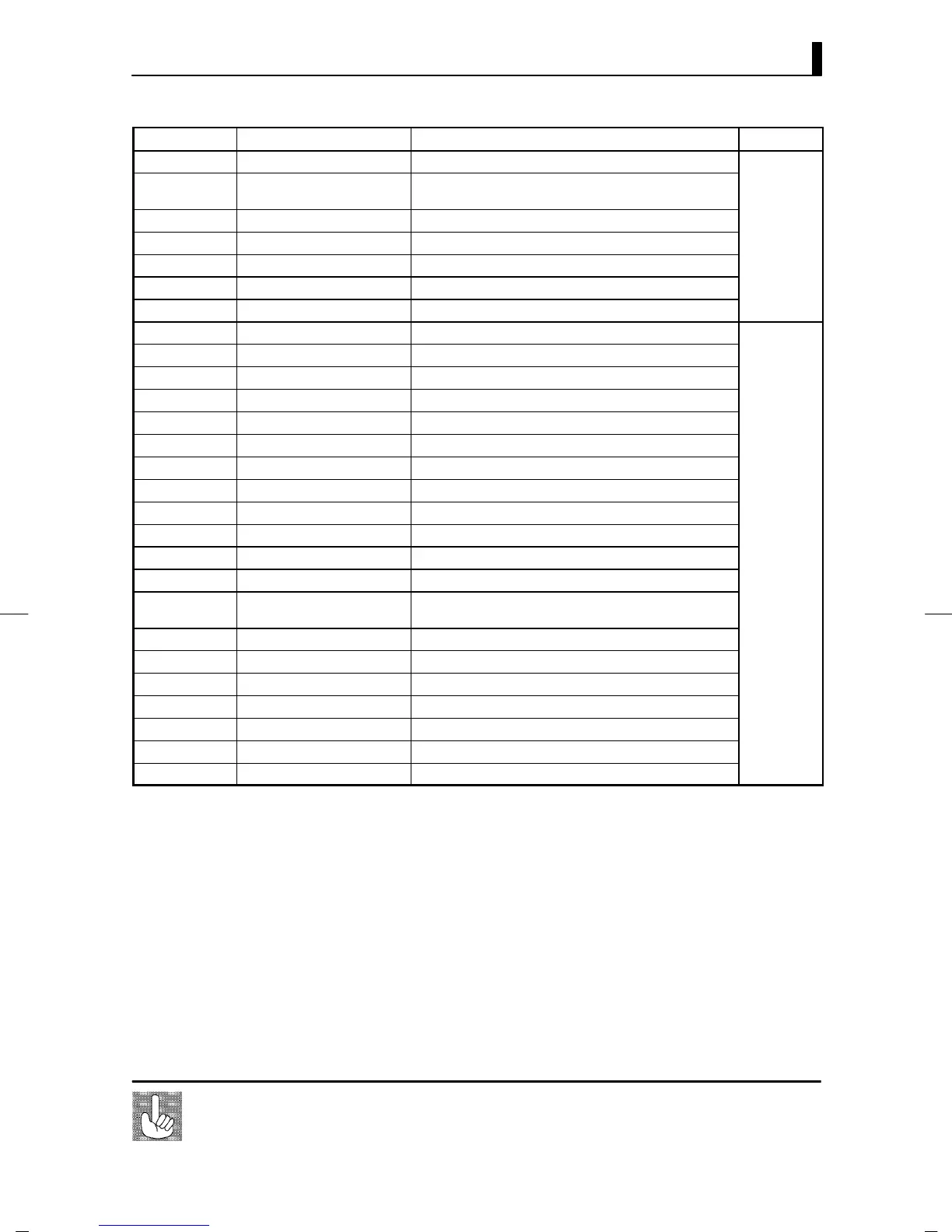
Parameter No. Parameter Data Setting and Monitor Range Mode
00 PV monitor
*1
Scaling lower limit -10% to scaling upper limit +10%
86 SP monitor during SP
*1
ramp
SP lower limit to SP upper limit
04 MV monitor (heat)
*1
-5.0 to 105.0
42 MV monitor (cool)
*1
0.0 to 105.0
Level 0
24 Remote SP monitor
*1
Scaling lower limit to scaling upper limit
14 Valve opening monitor
*1
-10.0 to 110.0
01 Set point
SP lower limit to set point upper limit
10 Set point 0
SP lower limit to SP upper limit
11 Set point 1
SP lower limit to SP upper limit
12 Set point 2
SP lower limit to SP upper limit
13 Set point 3
SP lower limit to SP upper limit
02 Alarm value 1 -1999 to 9999
03 Alarm value 2
-1999 to 9999
41 Alarm value 3
-1999 to 9999
19 Proportional band
0.1 to 999.9
20 Integral time
0 to 3999
21 Derivative time
0 to 3999
22 Cooling coefficient
0.01 to 99.99
Level 1
09 Dead band
-19.99 to 99.99
87 Position-proportional dead
band
0.1 to 10.0
23 Manual reset value
0.0 to 100.0
06 Hysteresis (heat)
0.01 to 99.99
43 Hysteresis (cool)
0.01 to 99.99
07 Control period (heat)
1to99
08 Control period (cool)
1to99
17 Heater current monitor
*1
0.0 to 55.0
18 Heater burnout alarm
0.0 to 50.0
*1 Possible only during reading
*2Duringtemperatureinput,therangebecomestherangeofuseoftheselectedsensor.
*3 During heating and cooling control, the range becomes 0.0 to 105.0.
*4 During position-proportional control, the range becomes 1 to 3999.
Currently, if a command is used for invalid parameters (parameters that do not sat-
isfy the conditions of use in Chapter 5), the “undefined” error (end code: 1C) is out-
put.
About invalid
parameters
*2
*3
*4