CHAPTER 6 USING THE COMMUNICATIONS FUNCTION
E5EK
6--8
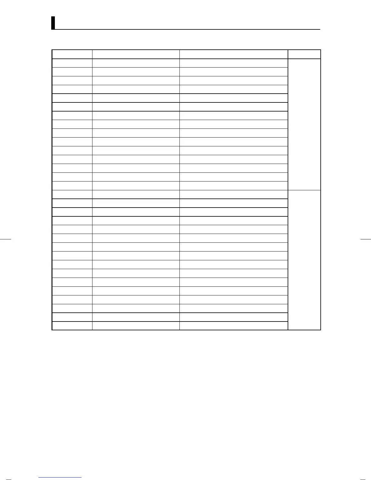
Parameter No. Parameter Data Setting Range Mode
44 SP ramp time unit
0: Minutes, 1: Hours
45 SP ramp set v alue
0 to 9999
46 LBA detection time
0 to 9999
47 MV at stop
-5.0 to 105.0
48 MV at PV error
-5.0 to 105.0
50 MV upper limit
MV lower limit +0.1 to 105.0
49 MV lower limit
-5.0 to MV upper limit -0.1
51 MV change rate limit
0.0 to 100.0
Level 2
56 Input digital filter
0 to 9999
88 Open/close hysteresis
0.1 to 20.0
25 Alarm 1 hysteresis
0.01 to 99.99
26 Alarm 2 hysteresis
0.01 to 99.99
52 Alarm 3 hysteresis
0.01 to 99.99
53 Input shift upper limit
-199.9 to 999.9
54 Input shift lower limit
-199.9 to 999.9
57 Input type
0to21
59 Scaling upper limit
Scaling lower limit +1 to 9999
58 Scaling lower limit
-1999 to scaling upper limit -1
60 Decimal point
0to3
30 _C/_F selection
0:_C, 1 : _F
61 Control output 1 assignment
0to6
62 Control output 2 assignment
0to6
63 Auxiliary output 1 assignment
2to9
64 Auxiliary output 2 assignment
2to9
etup
65 Alarm 1 type
1to11
66 Alarm 1 open in alarm
0: closed in alarm, 1: open in alarm
67 Alarm 2 type
1to11
68 Alarm 2 open in alarm
0: closed in alarm, 1: open in alarm
69 Alarm 3 type
1to11
70 Alarm 3 open in alarm
0: closed in alarm, 1: open in alarm
71 Direct/Reverse operation
0: Reverse operation, 1: Direct operation
*1 During heating and cooling control, the range becomes -105 to 105.0. During position-proportional control, you can select
between
*1 0: Hold/1: Open/2: Close. ( Default is 0: Hold.)
*2 During heating and cooling control, the range becomes 0.0 to 105.0.
*3 During heating and cooling control, the range becomes -105.0 to 0.0
*4 See page 5-26.
*5 0: Control output (heat), 1: Control output (cool), 2: to 4: Alarms 1 to 3, 5: HBA, 6: LBA, 7 to 9: Errors 1 to 3
*6 See page 5-30.
*1
*1
*2
*3
*4
*5
*5
*5
*5
*6
*6
*6