SPECIFICATIO NS
E5EK
A-- 3
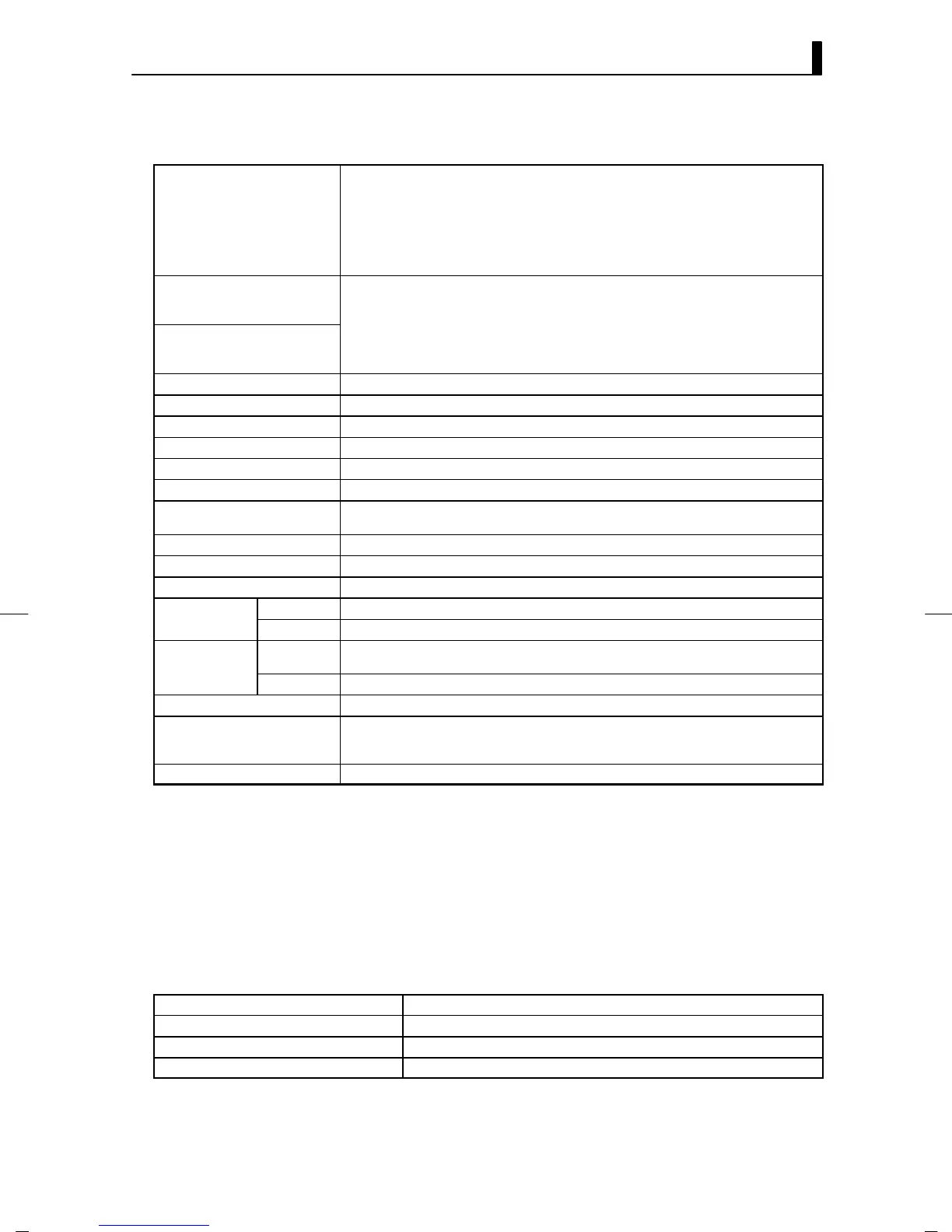
JCharacteristics
Indication Accuracy
Thermocouple:
(±0.3% of indication value or ± 1°C, whichever greater) ± 1 digit max.
(*1)
Platinum resistance thermometer:
(±0.2% of indication value or± 0.8°C whichever greater)± 1 digit max.
Analog input: ±0.2%± 1 digit max.
CT input: 5%FS 1 digit max.
Potentiometer: 5%FS 1 digit max.
Remote SP: 0.2%FS 1 digit max.
Temperature variation influence
(*2)
Platinum resistance thermometer:
(±1% of PV or ± 2°C, whichever greater) ±1 digit max.
Thermocouple (R, S, B, W):
°
Voltage variation influence
(*2)
(±1% o
P
or ±10°C, whichever greater) ±1 digit max.
Other thermocouples (K1, K2, J1, J2, E, N, T, L1, L2, U, PLII):
(±1% of PV or ±4°C, whichever greater) ±1 digit max.
Analog input (current, voltage, or remote SP input): ±1%FS±1 digit max.
Hysteresis 0.01 to 99.99% FS (in units of 0.01% FS)
Proportional Band (P) 0.1 to 999.9% FS (in units of 0.1% FS)
Integral (reset) Time (I) 0 to 3999 s (in units of 1 second)
Derivative (rate) Time (D) 0 to 3999 s (in units of 1 second)
Control Period 1 to 99 s (in units of 1 second)
Manual Reset Value 0.0 to 100.0% (in units of 0.1%)
Alarm Setting Range
--1999 to 9999 or -199.9 to 999.9 (decimal point position dependent on input type or result of
scaling)
Sampling Period Temperature input: 250 ms, Analog input: 100 ms, Sub-input : 1s
Insulation Resistance 20 MΩ min. (at 500 VDC)
Dielectric Strength 2000 V AC, 50/60Hz for 1 min (between terminals of different polarities)
ibration
Malfunction 10 to 55 Hz, 10 m/s
2
(approx. 1G) for 10 min each in X, Y, and Z directions
Resistance
Destruction 10 to 55 Hz, 20 m/s
2
(Approx. 2G) for 2hrs each in X, Y, and Z directions
Shock Resis-
Malfunction
200 m/s
2
min. (approx. 20G), 3 times each in 6 directions (100 m/s
2
(approx. 10G) applied to
the relay)
tance
Destruction 300 m/s
2
min. (Approx. 30G), 3 times each in 6 directions
Weight Approx. 320 g, mounting bracket: approx. 65 g
Enclosure Ratings
Front panel: NEMA4 for indoor use (equivalent to IP66)
Rear case: IEC standard IP20
Terminals: IEC standard IP00
Memory Protection Non-volatile memory (number of writings : 100000 operations)
*1 The indication accuracy of the K1, T, and N thermocouples at a temperature of -100°Corlessis±2°C ±1 digit maximum.
The indication accuracy of the U, L1 and L2 thermocouples at any temperature is ±2°C ±1 digit maximum.
The indication accuracy of the B thermocouple at a temperature of 400°Corlessisunrestricted.
The indication accuracy of the R and S thermocouples at a temperature of 200°Corlessis±3°C ±1 digit maximum.
The indication accuracy of the W thermocouple is ±1 digit max. of whichever is the greater of ±0.3% or ±3°Coftheindi-
cated value.
The indication accuracy of the PLII thermocouple is ±1 digit max. of whichever is the greater of ±0.3% or ±2°Cofthe
indicated value.
*2 A m bient temperature: --- 10°Cto23°Cto55°C
Voltage range: --- 15 to +10% of rated voltage
*3 On a position-proportional control type, 1 to 3999.
F Heater Burnout Alarm
Max. heater current Single-phase 50 A V AC (see note 1)
Heater current value display accuracy 5%FS 1 digit max.
Heater burnout alarm setting range 0.1 to 49.9 A (in units of 0.1 A) see note 2)
Min. detection ON time 190 ms (see note 3)
Note: 1. Use the K2CU-FVVA-VGS (with gate input terminals) for the detection of three-phase heater burnout.
2. The heater burnout alarm is always O FF if the alarm is set t o 0.0A and always ON if the alarm is set to 50.0A.
3. No heater burnout detection or heater current value measurement is possible if the control output (heat) is ON for
less than 190ms.
(*3)