Chapter 4: System Installation
–
+
eCobra Robot
-
+
SmartController EX
–
GND
+
-
+
SmartVision MX
1
2
8
7
6
5
4
4
4
3
3
3
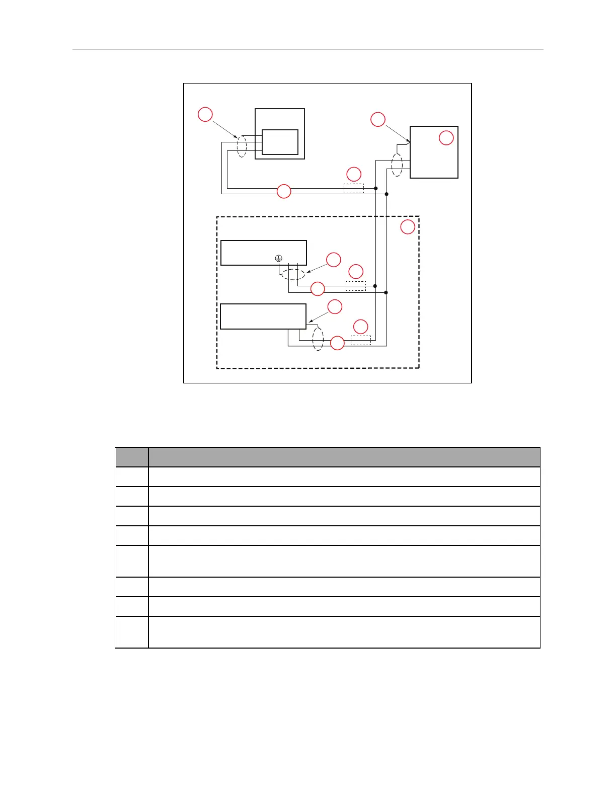
Figure 4-9. User-Supplied 24 VDC Cable, Power Supply
Table 4-9. User-Supplied 24 VDCCable, Power Supply Description
Item Description
1 User-suppliedPower Supply, 24 VDC
2 Optional Equipment
3 User-supplied, Shielded PowerCable
4 Circuit Protection, 8 Amax.
5 Shield - attach from user-supplied cable to ground screw on eCobra robot interface
panel.
6 Shield - attach from user-supplied cable to frame ground on power supply.
7 Shield - attach from user-supplied cable to left wire slot of SmartVision MX.
8 Shield - attach from user-supplied cable to side of SmartController EX using star
washer and M3 x 6 screw.
14402-000 Rev. F eCobra User's Guide 53