64 eCobra User's Guide 14402-000 Rev. F
4.9 Installing User-Supplied Safety Equipment
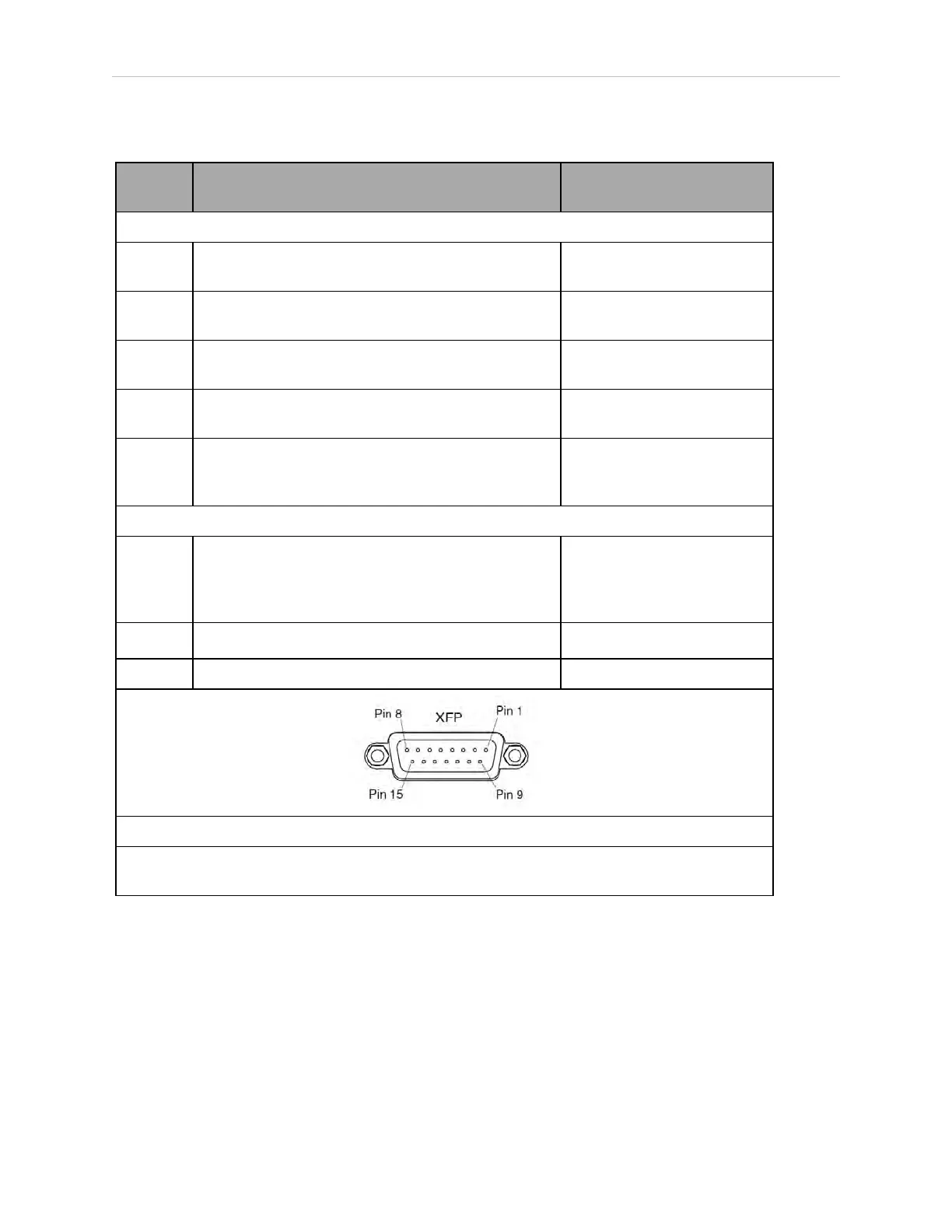
Table 4-17. Contacts Provided by the XFP Connector
Pin
Pairs
Description Requirements for User-
Supplied Front Panel
Voltage-Free Contacts Provided by Customer
1, 9 Front Panel E-Stop CH 1 User must supply N/C con-
tacts
2, 10 Front Panel E-Stop CH 2 User must supply N/C con-
tacts
3, 11 Remote Manual/Automatic switch CH 1.
Manual = Open Automatic = Closed
Optional - jumper closed for
Auto Mode-only operation
4, 12 Remote Manual/Automatic switch CH 2.
Manual = Open Automatic = Closed
Optional - jumper closed for
Auto Mode-only operation
6, 14 Remote High Power on/off momentary push-button User must supply moment-
ary push-button to enable
High Power to system
Non-voltage-Free Contacts
5, 13 System-Supplied 5 VDC and GND for High Power
On/Off Switch Lamp
User must supply lamp, or
use 1 W, 47 ohm resistor -
system will not operate if
not present
7, 15
a
Controller system 5 V power on LED, 5 V, 20mA Optional - indicator only
8 No connection
See the figure Front Panel Schematic on page 68 for a schematic diagram of the Front Panel.
a
Users must exercise caution to avoid inadvertently connecting 24 V signals to these pins,
because this will damage the electronics.
NOTE: The system was evaluated by Underwriters Laboratory with a Front
Panel. Using a substitute front panel could void UL compliance.
 Loading...


