Chapter 5: System Operation
Item Location Type Signal Range
8
IO Blox 6 Inputs 1073–1080
Outputs 0073–0080
9
IO Blox 7 Inputs 1081–1088
Outputs 0081–0088
10
IO Blox 8 Inputs 1089–1096
Outputs 0089–0096
a
For Multi-Robot systems, see Single and Multiple Robot Configuration Guide.
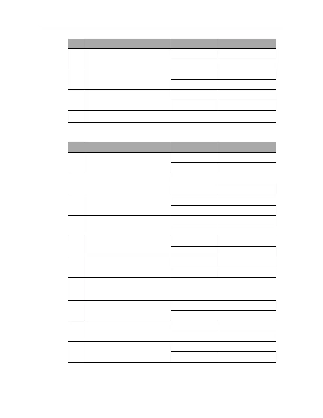
Table 5-5. Default Digital I/O Signal Configuration, Single Robot, with SmartController EX
Item Location Type Signal Range
1
SmartController EX (optional)
XDIO connector
Inputs 1001–1012
Outputs 0001–0008
2
Robot 1 XIO connector
a
On eAIB panel.
Inputs 1097–1108
Outputs 0097–0104
3
IO Blox 1 Inputs 1113–1120
Outputs 0105–0112
4
IO Blox 2 Inputs 1121–1128
Outputs 0113–0120
5
IO Blox 3 Inputs 1129–1136
Outputs 0121–0128
6
IO Blox 4 Inputs 1137–1144
Outputs 0129–0136
NOTE: The signal number sequence at this point jumps ahead -
it is not contiguous from IO Blox 4 to IO Blox 5.
7
IO Blox 5 Inputs 1289–1296
Outputs 0257–0264
8
IO Blox 6 Inputs 1297–1304
Outputs 0265–0272
9
IO Blox 7 Inputs 1305–1312
Outputs 0273–0280
14402-000 Rev. F eCobra User's Guide 85