Section 2 NS Series Functions 2-20 Special Functions
2-462
NS Series Programming Manual
1
2
3
4
5
6
7
8
9
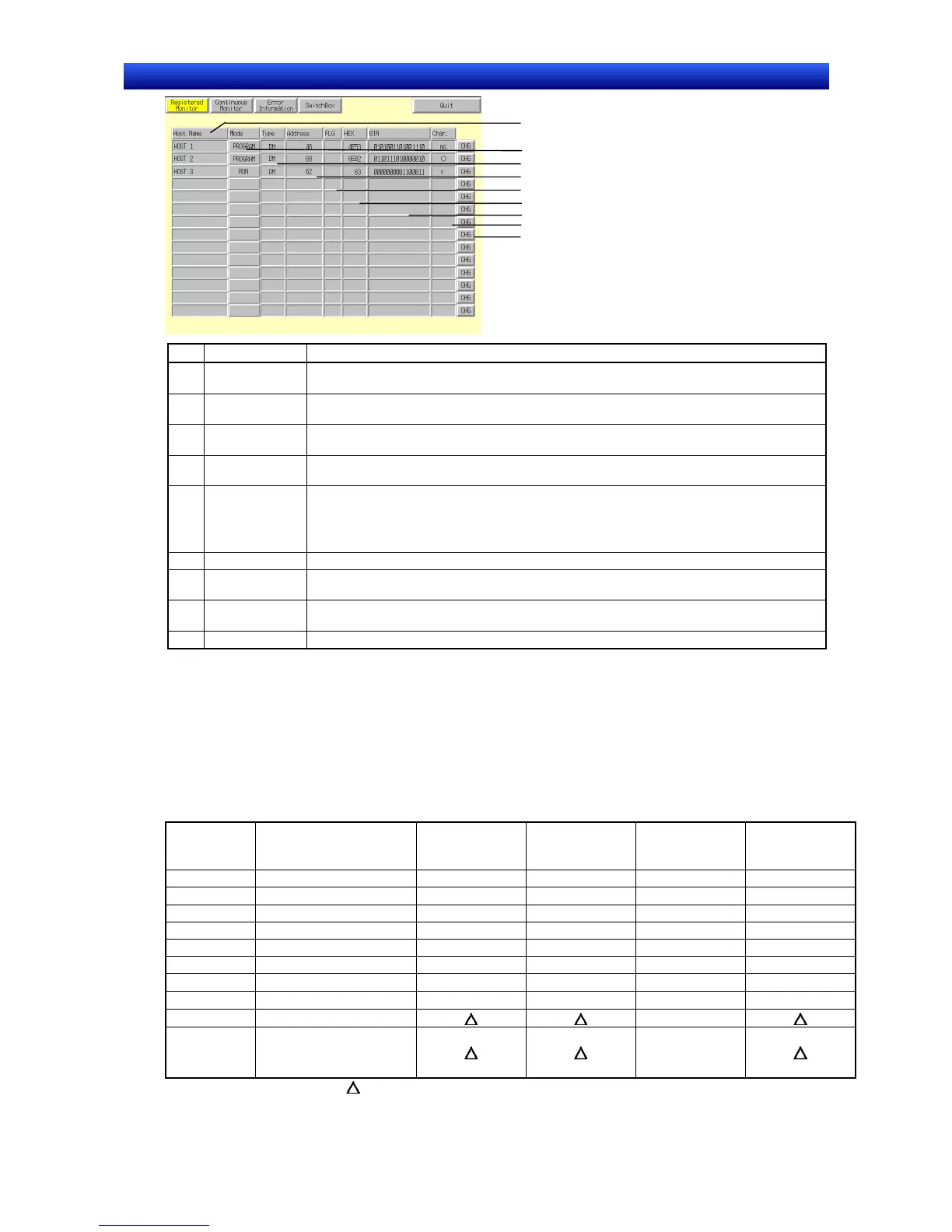
No. Setting Details
1 Host name Press Host name to display the Host Selection Dialog Box and select the Host. Host names set
using CX-Designer can be selected.
2 Mode
(See note 1.)
Press Mode to display the Change Mode Dialog Box. Switches to the specified PLC mode.
3 Type
(See note 2.)
Press Type to display the CH Type Selection Dialog Box. Sets the word type to be monitored.
4 Address
(See note 3.)
Press Address to display the CH Type Selection Dialog Box. Sets the addresses to be monitored.
5 FLG
(See note 4.)
If TIM or CNT are set as the type, the following data will be displayed.
When TU or CU are counted: o
For force on using device monitor: S
For force off using device monitor: R
6 HEX Displays the contents of the specified address in hexadecimal.
7 BIN
(See note 5.)
Displays the contents of the specified address in binary.
8 Characters
(See note 6.)
Displays the contents of the specified address in characters.
9 Change Switches to the screen for changing current values.
Note 1. NS5 PTs display P for Program, M for Monitor, and R for Run.
2. Appears as Type for NS10, NS8, and NS5 PTs.
3. Appears as Address for NS10 and NS8 PTs and as add. for NS5 PTs.
4. Appears as F for NS10, NS8, and NS5 PTs.
5. Blank for the NS5 PTs.
6. Appears as char for NS5 PTs.
Words Displayed on Registered Monitor Screen
Words that can be displayed on the device monitor function Registered Monitor Screen depend on the
PLC model. These word areas are shown in the following table.
Symbol Word area CJ1(-H), CS1(-H)
C200HX/HG/
HE-E/-ZE
CQM1, CPM1A,
CPM2A, CPM2C,
C200HS
CQM1H
DM DM Area
CIO I/O Area
TIM Timer Area
CNT Counter Area
HR HR area
AR AR Bit and Auxiliary Areas
LR Link Area
−
WR Work Area
− − −
EM EM Area (current bank)
−
EM0
to
EM18
EM Area (bank 0)
to
EM Area (bank 18)
−
: Can be displayed, : No area, : Can be displayed within the existing ranges
× : Cannot be displayed
The CS/CJ-series Task Flag (TK) and clock pulse (P) cannot be displayed.

 Loading...


