Section 2 NS Series Functions 2-20 Special Functions
2-492
NS Series Programming Manual
No. Item Description
2 Bit Address Setting Edit the bit to be sampled.
Press the and buttons to switch the data area. The CIO, WR, HR, AR, TU,
CU, CF, DM, EM, or EM0 to EM18 data area can be selected.
Press the Address Field to display a tenkey pad. Input the address to be moni-
tored. Addresses can be set between 0.0 and 32767.15, but be sure to input an
address that is valid in the connected PLC.
If a CF address is being set, select the address from the displayed list.
3 Set Sets the bit selected in the Bit Address Setting Field in the Address List.
4 Delete Deletes the selected address from the Address List.
N
N
N
o
o
o
t
t
t
e
e
e
♦
Always press the Set Button to set the edited Bit Address Setting in the Address List.
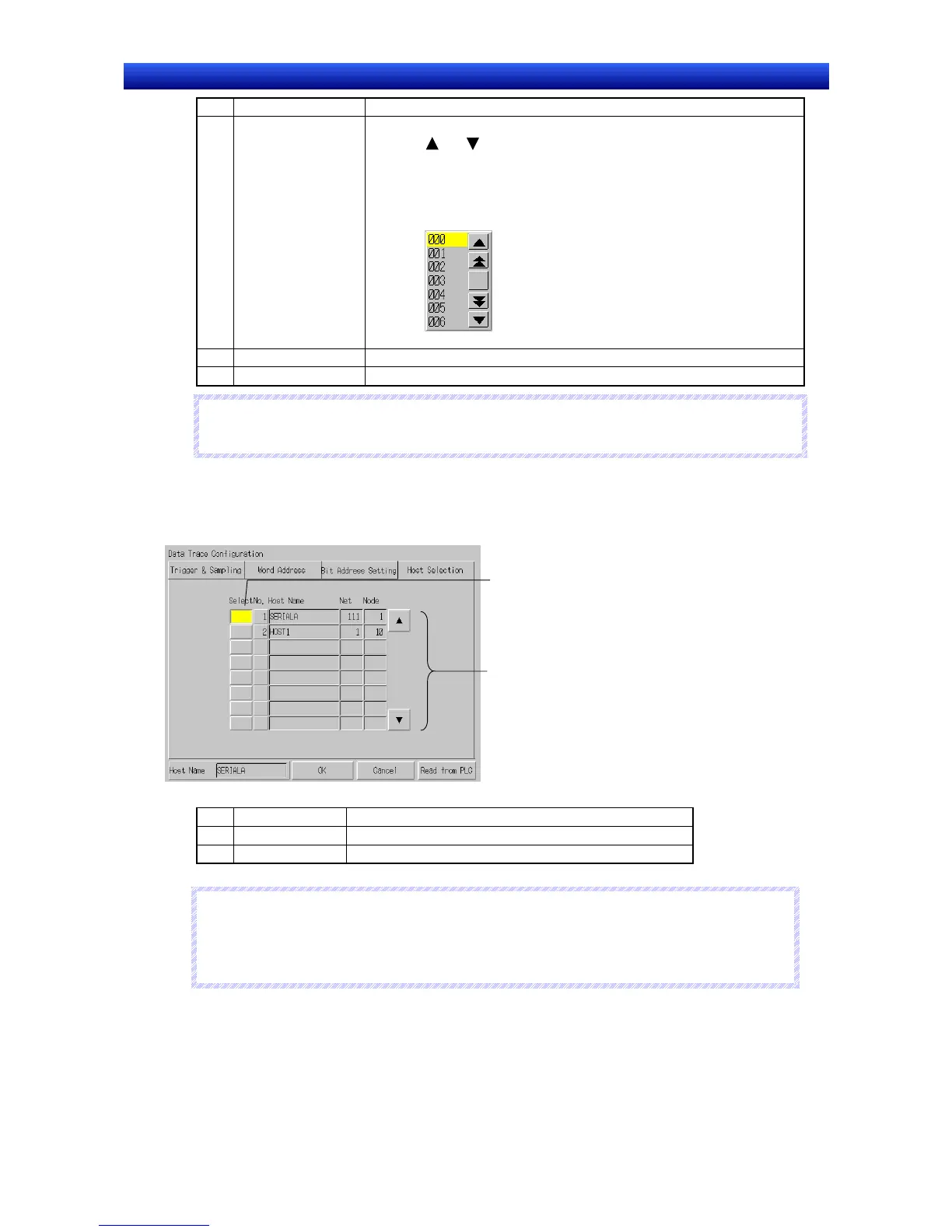
Selecting the Host
The Host Selection Tab Page sets the host in which the data trace will be executed.
1. Open the Data Trace Configuration Screen’s Host Selection Tab Page.
1
2
No. Item Description
1 Select Selects the host.
2 Host Name Lists the hosts registered in the project.
N
N
N
o
o
o
t
t
t
e
e
e
♦
When a host has not been selected, the host at the top of the list is selected by default.
♦
The data tracing is supported by the CS/CJ Series (except the CP1) and the NSJ Series Con-
troller section. Select a host that is set to one of these PLCs.
Executing the Data Trace
This section explains how to execute the data trace.
Before executing a data trace, the data trace parameters must be set in the Data Trace Configuration
Screen.

 Loading...


