5-35
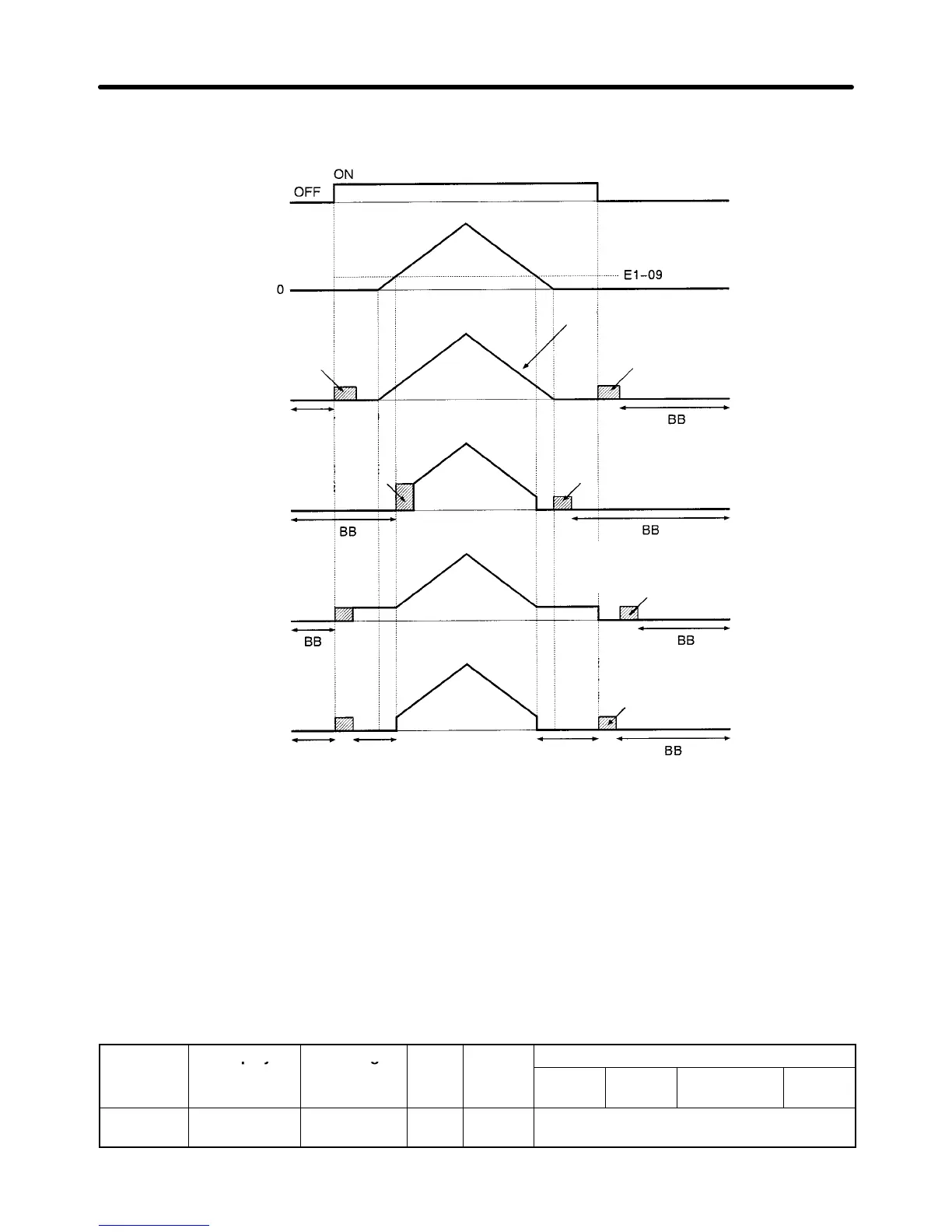
The timing of the initial excitation function depends on the zero-speed operation method selected with
b1-05, as shown in the following diagrams.
Run command
Frequency reference
from analog input
• b1-05 = 1
(STOP)
• b1-05 = 0
(RUN at Frequency
Ref)
• b1-05 = 2
(RUN
at Min Frequency)
• b1-05 = 3
(RUN at Zero RPM)
Initial excitation
BB
(Baseblock)
Initial excitation from E1-09
BB Zero speed Zero speed
Initial excitation
Inverter’s internal frequency reference
(Soft start input)
After the frequency reference falls below
E1-09, initial excitation starts when the
motor speed drops below b2-01.
After the run command goes OFF
, initial
excitation starts when the motor speed
drops below b2-01.
After the run command goes OFF
, initial
excitation starts when the motor speed
drops below b2-01.
Note 1. Initial excitation is started from b2-01 (excitation level) when decelerating.
A setting of b2-01 < E1-09 is valid only with flux vector control.
Note 2. The current level for the initial excitation function is set in E2-03 (no-load current). The DC
braking (injection) current (b2-02) isn’t used with flux vector control and can’t be set.
5-4-3 Auto-tuning
H Inverter Input Voltage Setting (E1-01)
Set
the Inverter
’
s input voltage (E1-01) to match the power
supply voltage; it cannot be changed during
operation. This setting is used as the reference value for functions such as the protection functions.
Parameter Display Setting Units Default
Valid access levels
number
range setting
V/f
Control
V/f with
PG
Open Loop
Vector
Flux
Vector
E1-01 Input Voltage 155 to 255
(310 to 510)
VAC 200
(400)
Quick-start, Basic, or Advanced
Basic Operation Chapter
5