6-97
• The
multi-function outputs can be set to monitor any of the U1 Inverter status items by setting the last
two digits of the parameter number (U1-).
Refer to page 3-12 for a table listing all of these U1 settings.
• The
Inverter
’
s status
monitor item U1 can be output as multi-function analog output. Set the parame
-
ters
H4-01 and H4-03 (AO Ch1 Select and AO Ch2 Select) to the right side of the of
“U1” constants in
the
table on page
3-12
of this manual. The setting range is between 1 and 38, but the following num
-
bers cannot be set: 4, 10, 11, 13, 14, 25, 28, 29, 30, 31, 34, 35.
D Adjusting the Monitor Output
Parameter Display name Setting Units Default
Valid access levels
number
range setting
V/f
Control
V/f with
PG
Open Loop
Vector
Flux
Vector
H4-02 Terminal 21 Gain 0.00 to 2.50 Factor 1.00 Basic or Advanced
H4-03 Terminal 21 Bias –10.0 to 10.0 % 0.0 Basic or Advanced
H4-05 Terminal 23 Gain 0.00 to 2.50 Factor 0.50 Basic or Advanced
H4-06 Terminal 23 Bias –10.0 to 10.0 % 0.0 Basic or Advanced
Note These parameters can be changed during operation.
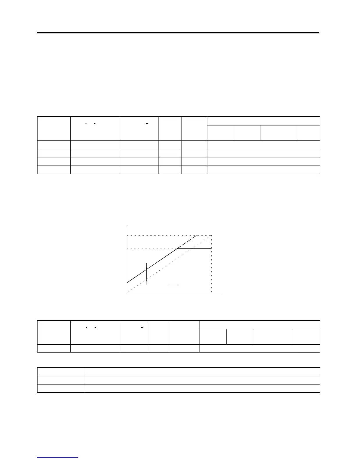
• For
the output gain, set what multiple of 10 V will correspond to a 100% output of the monitored
item.
• For the output bias, set the amount that the output characteristic will be shifted vertically.
Set this amount as a percentage, with 10 V corresponding to 100%.
Output voltage
Gain × 10 V
Bias
10
100
V
Monitored item
0%
0 V
100%
10 V
D Multi-function Analog Output Signal Level
Parameter Display name Setting Units Default
Valid access levels
number
range setting
V/f
Control
V/f with
PG
Open Loop
Vector
Flux
Vector
H4-07 AO Level Select 0 or 1 --- 0 Basic or Advanced
Note This parameter cannot be changed during operation.
Setting Function
0 0 to +10 V (Absolute value output)
1 0 to ±10 V
• This signal level setting applies to analog outputs 1 and 2 (terminals 21 and 23).
• When
the 0- to
±
10-V signal level is used to output speed values (frequency reference, output frequen
-
cy, or motor speed), positive voltage indicates Inverter output in the forward direction and negative
voltage indicates Inverter output in the reverse direction. (Assuming a bias setting of 0.0.)
Advanced Operation Chapter
6