2-41
H PG Speed Control Card Terminal Blocks
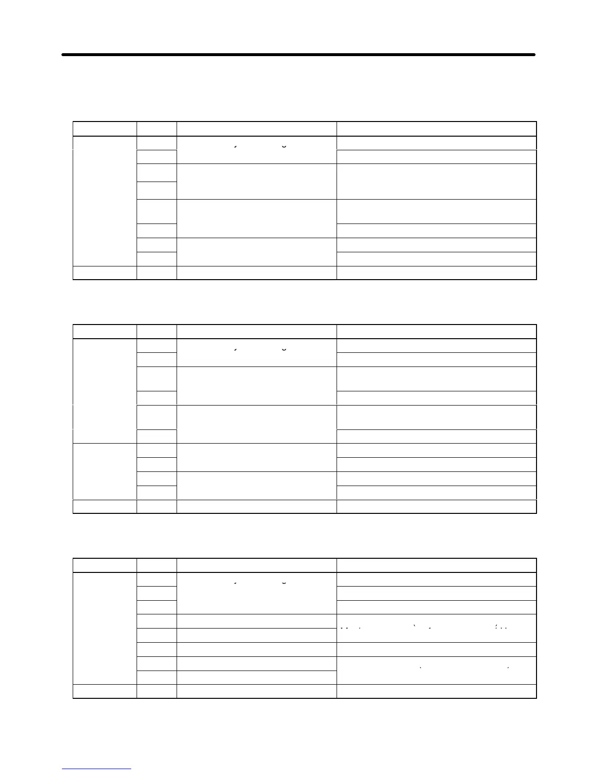
D 3G3FV-PPGA2 (For V/f With PG Feedback Mode Only)
Terminal No. Contents Specifications
TA1
1
Power supply for pulse generator
12 VDC (±5%), 200 mA max.
2
0 VDC (GND for power supply)
3
+12-V/open collector switching
Terminal for switching between12-V voltage
or open
collector input, short across 3 and 4.
5
Pulse input terminal
H: +4 to 12 V; L: +1 V max. (Maximum
response frequency: 30 kHz)
6 Pulse input common
7
Pulse motor output terminal
12 VDC (±10%), 20 mA max.
8 Pulse monitor output common
TA2 (E) Shielded-wire connection terminal ---
D 3G3FV-PPGB2 (For Flux Vector Control Mode Only)
Terminal No. Contents Specifications
TA1
1
Power supply for pulse generator
12 VDC (±5%), 200 mA max.
2
0 VDC (GND for power supply)
3
A-phase pulse input terminal
H: +8 to 12 V; L: +1 V max. (Maximum
response frequency: 30 kHz)
4 Pulse input common
5
B-phase pulse input terminal
H: +8 to 12 V; L: +1 V max. (Maximum
response frequency: 30 kHz)
6 Pulse input common
TA2
1
A-phase monitor output terminal
Open collector output, 24 VDC, 30 mA max.
2 A-phase monitor output common
3
B-phase monitor output terminal
Open collector output, 24 VDC, 30 mA max.
4 B-phase monitor output common
TA3 (E) Shielded-wire connection terminal ---
D 3G3FV-PPGD2 (For V/f With PG Feedback Mode Only)
Terminal No. Contents Specifications
TA1
1
Power supply for pulse generator
12 VDC (±5%), 200 mA max. (see note)
2
0 VDC (GND for power supply)
3 5 VDC (±5%), 200 mA max. (see note)
4 Pulse input + terminal
Line driver input (RS-422 level input)
Maximum response frequency: 300 kHz
6 Common terminal ---
7 Pulse monitor output + terminal
Line driver output (RS-422 level output)
8 Pulse monitor output – terminal
TA2 (E) Shielded-wire connection terminal ---
Note 5 VDC and 12 VDC cannot be used at the same time.
Installation Chapter
2