3-12
S Conditions for Monitoring
The
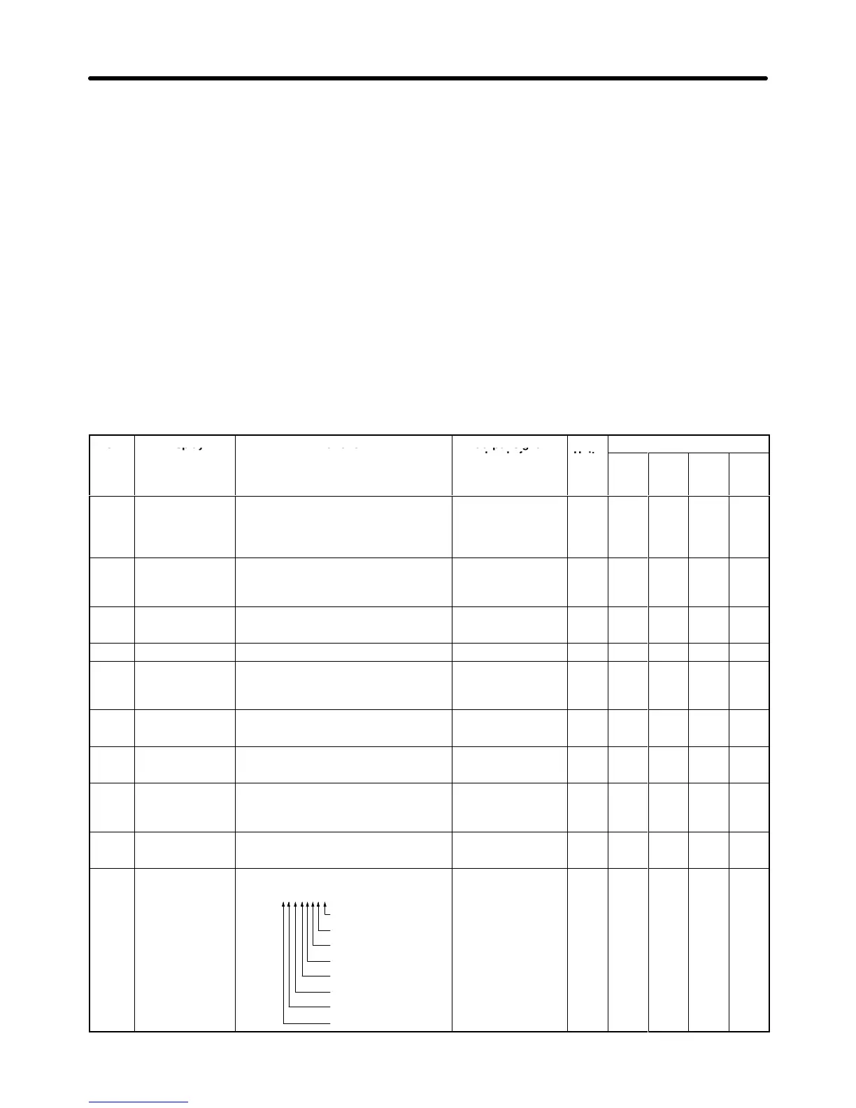
following tables show the items that can be monitored in operation mode. The table’
s “V
alid access
levels” column indicates whether an item can be monitored in a particular access level and control
mode. The codes in this column have the following meanings.
Q: These items can be monitored in all access levels. (Quick-start, Basic, and Advanced)
B: These items can be monitored in the Basic and Advanced access levels.
A: These items can be monitored in the Advanced access level only.
X: These items cannot be monitored in the control mode shown.
The
output signal levels for multi-function analog outputs shown in the table are for a gain of 100.0 and a
bias of 0.00.
Status Monitor
Item Display Function Output
signal
levels for
multi-function
analog outputs
Units
V/f V/f
w/PG
Open
Vec-
tor
Flux
Vec-
tor
U1-01
Frequency Ref
Monitors/sets the frequency reference
value.
The display units can be set with param
-
eter o1-01.
10 V
:
Max. frequency
(0 to
±
10 V possible)
0.01
Hz
Q Q Q Q
U1-02
Output Freq
Monitors the output frequency
.
The display units can be set with param
-
eter o1-01.
10 V
:
Max. frequency
(0 to
±
10 V possible)
0.01
Hz
Q Q Q Q
U1-03
Output Current
Monitors the output current. 10 V
: Rated current
(0 to +10 V output)
0.1 A
Q Q Q Q
U1-04
Control Method
Shows which control mode is set.
Can’t be output.
--- Q Q Q Q
U1-05
Motor Speed
Monitors the motor speed. 10 V
:
Max. frequency
(0 to
±
10 V possible)
0.01
Hz
X Q Q Q
U1-06
Output V
oltage
Monitors the Inverter
’
s internal output
voltage reference value.
10 V
: 200 (400) V
AC
(0 to +10 V output)
0.1 V
Q Q Q Q
U1-07 DC Bus Voltage
Monitors the DC voltage of the Inverter
’s
internal main circuit.
10 V
: 400 (800) VDC
(0 to +10 V output)
1 V
Q Q Q Q
U1-08 Output kWatts
Monitors the output power
. (This is an in
-
ternally detected value.)
10 V
:
Max. motor capacity
(0 to
±
10 V possible)
0.1
kW
Q Q Q Q
U1-09 T
orque Reference
Monitors the internal torque reference
value when vector control is used.
10 V
: Rated torque
(0 to
±
10 V possible)
0.1% X X Q Q
U1-10
Input T
erm Sts
(Input terminal
status)
Shows the ON/OFF status of inputs.
U1-10=00000000
1: T
erminal 1 ON
1: T
erminal 2 ON
1: T
erminal 3 ON
1: T
erminal 4 ON
1: T
erminal 5 ON
1: T
erminal 6 ON
1: T
erminal 7 ON
1: T
erminal 8 ON
Can’t be output.
--- Q Q Q Q
Preparing for Operation Chapter
3