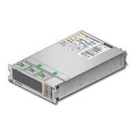
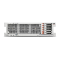
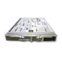
Remove the Front Indicator Panel Cable
2.
Take the necessary ESD precautions.
See “Prevent ESD Damage” on page 61.
3.
Power off the server and switch off the appropriate PDU circuit breakers.
See “Removing Power From the Server or Domain” on page 69.
4.
From the rear of the server, remove the SPs, and unseat the SP tray from the
impacted chassis.
See “Servicing SPs” on page 117 and “Servicing SP Trays” on page 243.
5.
Remove and unseat the appropriate components from the impacted chassis.
■
If the cable you are replacing is in the CMIOU chassis, remove the top four CMIOUs and
unseat the lower four CMIOUs in the chassis. See “Servicing CMIOUs” on page 83.
■
If the cable you are replacing is in the switch chassis, remove the top three switch
units and unseat the lower three switch units in the chassis. See “Servicing Switch
Units” on page 189.
6.
Remove the required fan modules.
If the cable you are replacing is in the CMIOU chassis, remove the four left fan modules. See
“Servicing Fan Modules (CMIOU Chassis)” on page 179.
7.
Remove of the interconnect assemblies from the front of the affected chassis.
See “Servicing Internal Interconnect Assemblies” on page 297, “Servicing External
Interconnect Assemblies” on page 305 (SPARC M7-16), and “Servicing SP Internal
Interconnect Assemblies” on page 285.
8.
Remove the front indicator panel.
See “Servicing the Front Indicator Panel” on page 217.
9.
If the cable you are replacing is in the CMIOU chassis, remove the left CMIOU
chassis fan cable assembly.
See “Servicing a CMIOU Chassis Fan Cable Assembly” on page 207.
10.
Release the Molex connector.
228 SPARC M8 and SPARC M7 Servers Service Manual • September 2017
 Loading...
