318
DP-2330/3030
MAR 2005
Ver.2.1
DP-2310/3010
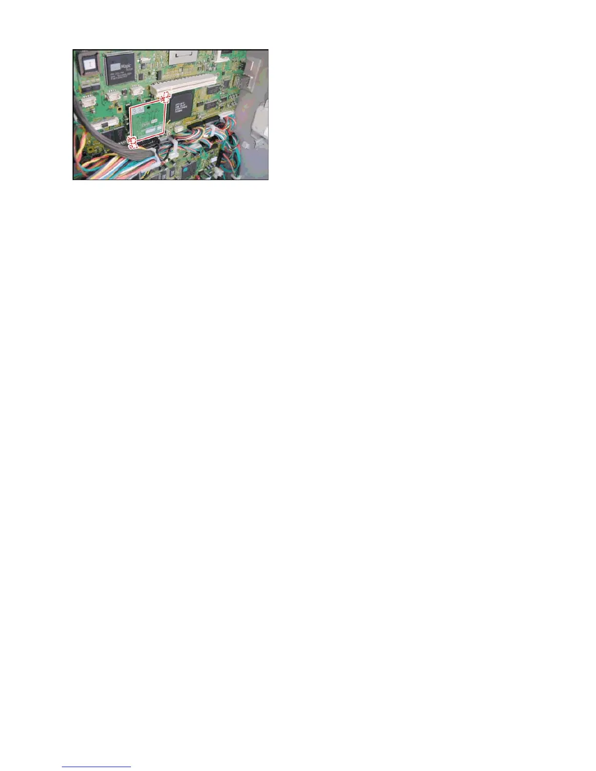
(3) Remove the Black Pin Protector from Slot 1
(CN62), if it was pre-installed.
(4) Install 2 PC Board Supporters for the Slot 1 on
the SC PC Board.
(5) Install the Program Expansion Board into Slot
1 (CN62) on the SC PC Board and secure with
the Supporters.
Note:
The Program Extension F-ROM Board must
always be installed into Slot 1 (CN62) for the PCL
or PCL/PS Printer Option to function.
(6) Proceed with the installation of other options.
If finished, close and secure the Rear Cover and
reinstall remaining Covers.
(7) Plug the AC Power Cord into the wall outlet and
turn the Main Power Switch on the Back and the
Power Switch on the Left Side of the machine to
the ON position.
(8) Reconnect the Telephone Line Cable if it was
disconnected.

 Loading...