EasyManua.ls Logo

Parker PD-04 Series - Page 212

Parker PD-04 Series
286 pages
To Next Page IconTo Next Page
To Previous Page IconTo Previous Page
Loading...
Parker Hannifin
P series User Guide 210
0x2211
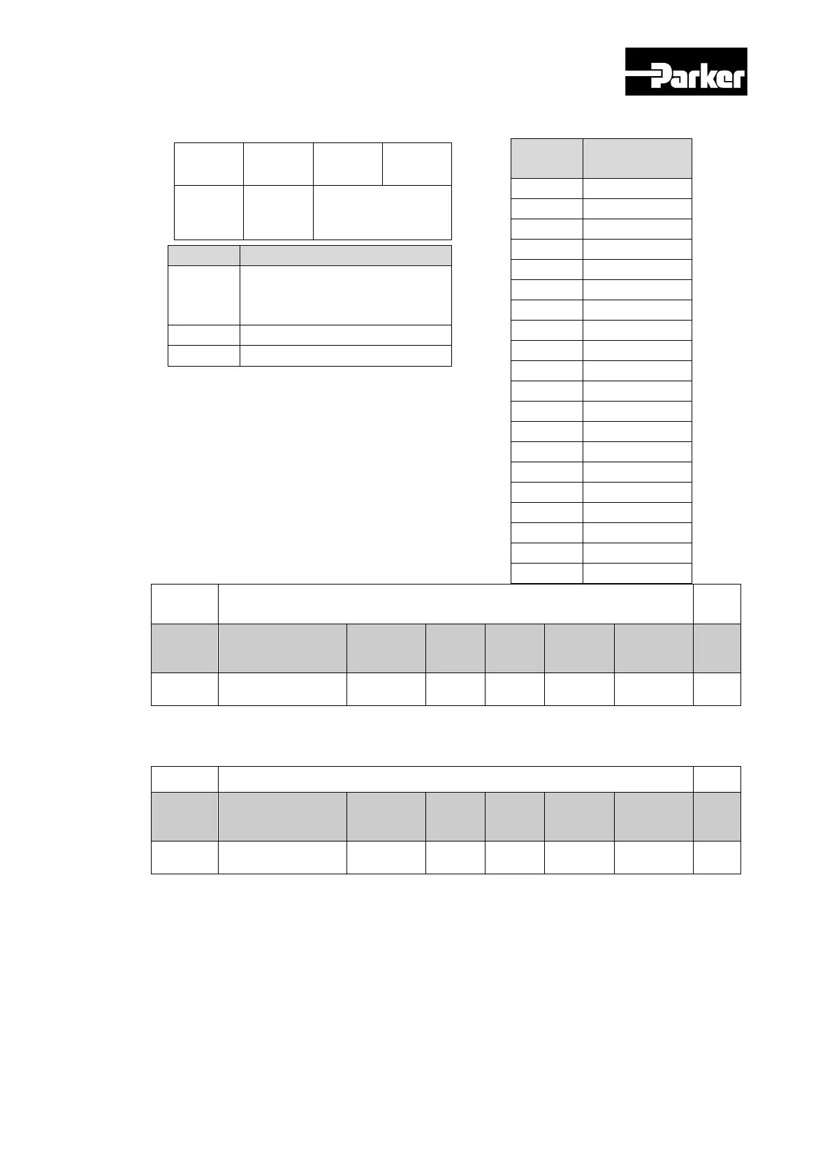
Digital Output Signal 2 Selection
ALL
Variabl
e
Format
Setting Range
Default
Value
Unit
Acces
sibility
PDO
Allocati
on
Change
Property
Stor
e
UINT
0 to 0xFFFF
0x0003
-
RW
No
Power
Resupply
Yes
Allocates the function of I/O connector‘s digital output signal 2, and sets the output
signal level. See the descriptions on 0x2210 for more detailed explanation.
0x2212
Digital Output Signal 3 Selection
ALL
Variabl
e
Format
Setting Range
Default
Value
Unit
Acces
sibility
PDO
Allocati
on
Change
Property
Stor
e
UINT
0 to 0xFFFF
0x8001
x
-
RW
No
Power
Resupply
Yes
Allocates the function of I/O connector‘s digital output signal 3, and sets the output
signal level. See the descriptions on 0x2210 for more detailed explanation.
Set
Value
Allocation
Signal
0x00
Not allocated
0x01
BRAKE
0x02
ALARM
0x03
READY
0x04
ZSPD
0x05
INPOS1
0x06
TLMT
0x07
VLMT
0x08
INSPD
0x09
WARN
0x0A
TGON
0x0B
INPOS2
0x10
ORG
0x11
EOS
0x12
IOUT0
0x13
IOUT1
0x14
IOUT2
0x15
IOUT3
0x16
IOUT4
0x17
IOUT5
8
0
0
1
CONTACT
B
BRAKE Allocation
bit
Setting Details
15
Signal output level setting
(0:CONTACT A, 1:CONTACT
B)
14~8
Reserved
7~0
Output signal allocation

Table of Contents

Related product manuals