LIFEPAK 15 Monitor/Defibrillator
Service Manual
Replacement Procedures
Backlight PCB (A08) Replacement
Section Menu Section Contents Procedures Back Index
196
8
Removing the Backlight PCB (A08)
To remove the backlight PCB from the front case:
1. Disassemble the case as described in Disassembling
the Case (p. 181).
2. Remove the interface PCB as described in Removing
the Interface PCB (A05) (p. 193).
3. Disconnect the backlight/interface PCB cable (W06)
(3206992-000). Press the connector locking tab and
disconnect the W06 cable from the interface PCB at
J37. Then place even pressure on the cable and ease
the W06 cable out of the connector on the Backlight
PCB.
4. Remove the two backlight inverter mounting screws
(202253-761). Discard the screws.
5. Lift the backlight inverter off of the display assembly
and disconnect the two end connectors from the LCD
display assembly.
6. Remove the inverter cover (3207252-001).
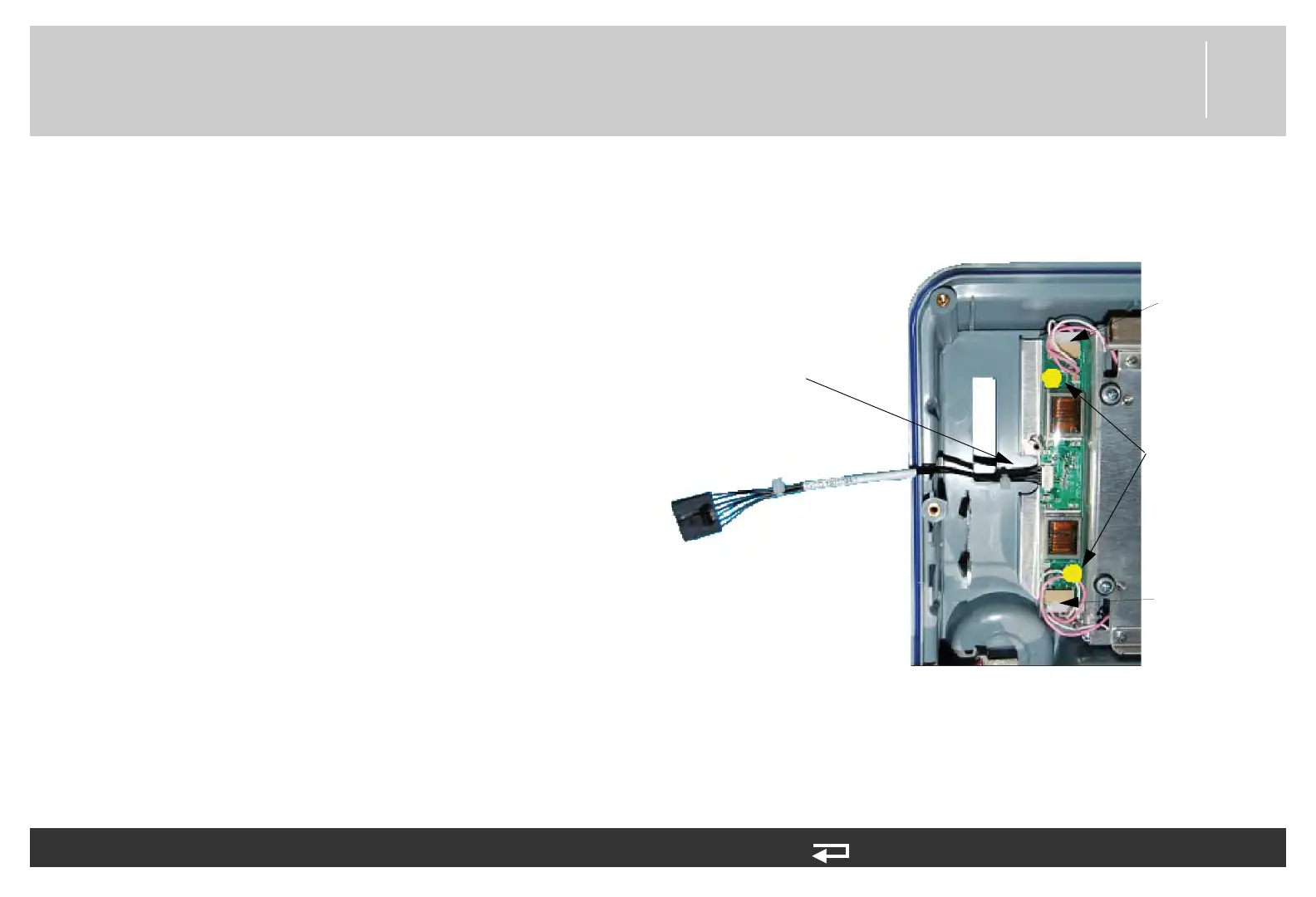
Figure 8.13—Screw location and cable connection for backlight PCB
screw locations
W06 - power connector
(
3206992-000)
LCD connection
point
LCD connection
point