LIFEPAK 15 Monitor/Defibrillator
Service Manual
Replacement Procedures
Backlight PCB (A08) Replacement
Section Menu Section Contents Procedures Back Index
197
8
Installing the Backlight PCB (A08)
To install the backlight PCB into the front case:
NOTE: If a new backlight PCB is required,
install the Backlight Inverter Repair
Kit (MIN 3305431-012).
1. Place the inverter cover (3207252-001) over the
backlight PCB.
2. Connect the two end connectors to the LCD display
assembly.
3. Connect the backlight/interface PCB cable (W06)
(3206992-000) to backlight power connector.
4. Place the backlight inverter on the display assembly
and install with two new screws (202253-761);
torque to 6.8 in-lb.
5. Feed excess length of LCD wires into backlight
inverter cover.
6. Install the interface PCB as described in Installing the
Interface PCB (A05) (p. 194).
7. Reassemble the case as described in Reassembling
the Case (p. 184).
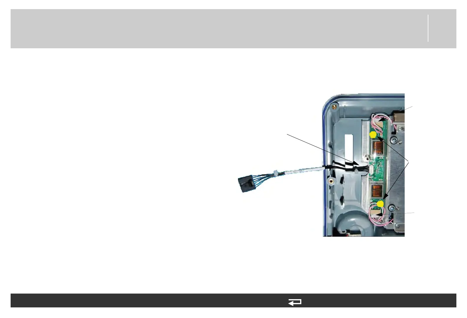
Figure 8.14—Screw location and cable connection for backlight PCB
screw locations
W06 - power connector
(
3206992-000)
LCD connection
point
LCD connection
point