LIFEPAK 15 Monitor/Defibrillator
Service Manual
Replacement Procedures
Inside Rear Case Diagrams
Section Menu Section Contents Procedures Back Index
231
8
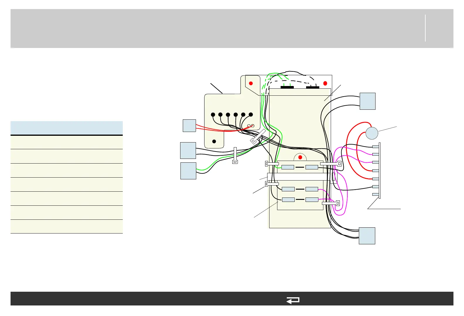
Energy Transfer Detail Diagram
Use this diagram to replace the
transfer relay assembly, biphasic
module/inductive resistor, energy
storage capacitor, and
A17 interconnect bracket.
Table 8.1—Interconnect bracket
A17 Interconnect Bracket Chart
Capacitor Neg 1 A17 Pin 1
Capacitor Pos 4 A17 Pin 4
A22 Biphasic J101 A17 Pin 3
A22 Biphasic J105 A17 Pin 6
A22 Biphasic J103 A17 Pin 9
Relay A1 (7) A17 Pin 7
Relay B1 (104) A22 BTE J104
X1 X2
B3 B2 B1 A1 A2 A3
A17 Interconnect Bracket
–
J18
J19
J21
J22
cable tie (222)
(6 places)
large cable tie (224)
+
+
–
J101
J103
J105
J108
J102
J104
J107 Not Used
P24
A14
Inductive
Resistor
A22
Biphasic
Module
A13 Transfer Relay
Assembly
A15 Energy Storage
Capacitor
To Therapy
PCB - P21
To Therapy
PCB - P18
P24 To Therapy
Connector
on Front Case
To Therapy
PCB - P22
To Therapy
PCB - P19
1 2 3
4 5 6
7 8 9
The wire colors are not the actual wire colors,
but are for graphic representation only.