LIFEPAK 15 Monitor/Defibrillator
Service Manual
Replacement Procedures
Inside Rear Case Diagrams
Section Menu Section Contents Procedures Back Index
230
8
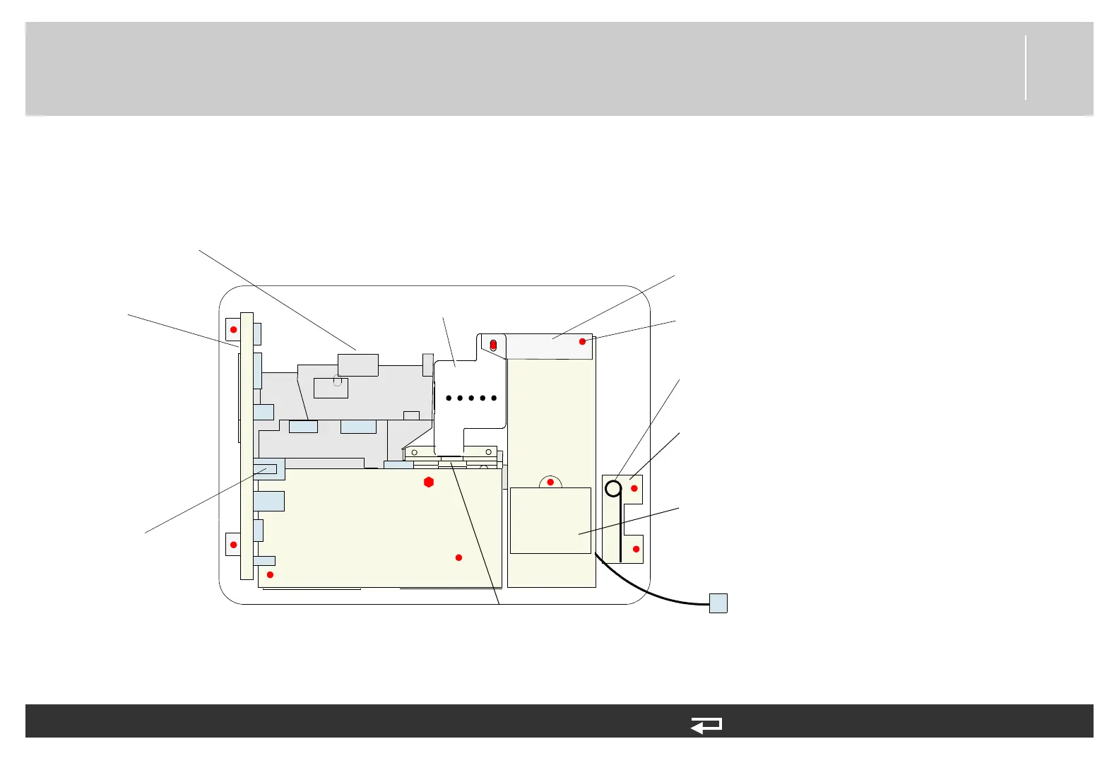
System (A01)/Therapy (A04) PCBs Removed
Use this diagram after removing the A01 system and A04 therapy PCBs as described in System (A01)/Therapy (A04) PCB
Assembly Replacement (p. 232).
A15 Energy
Storage
Capacitor
A06 OEM PCB Module
A17 Interconnect
Bracket
A14 Inductive
Resistor
P24
A13 Transfer Relay Assembly
A03 Power
PCB
J17
J08
J16/J25
J13
J15
J14
J11
JP5
JP1
J12
capacitor bracket
disassembly
screw (typical)
A13 Biphasic
Module
Relay bracket
CO2, SpO2, and NIBP
PCBs
J26