LIFEPAK 15 Monitor/Defibrillator
Service Manual
Replacement Procedures
Installing the System (A01)/Therapy (A04) PCB Assembly
Section Menu Section Contents Procedures Back Index
251
8
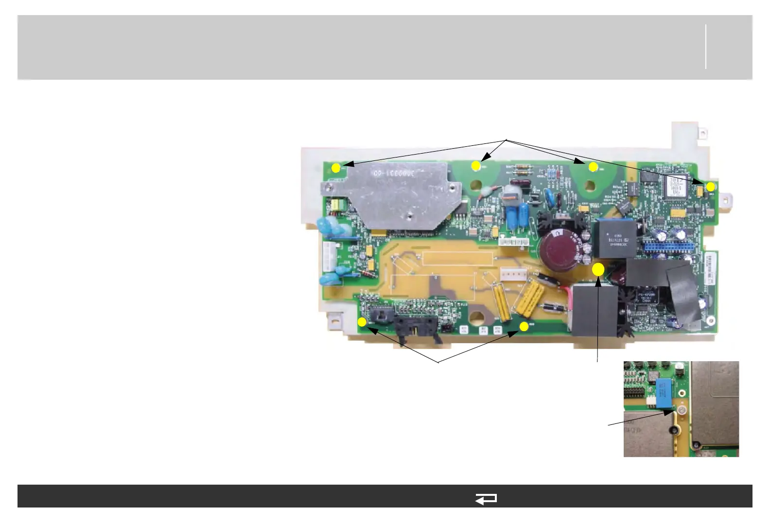
5. Align the therapy PCB with the
system PCB. Insert the 30 pin
header into J5 of system PCB and
align with screw holes in
mounting bracket. Ensure that the
spacer is protruding from hole in
therapy PCB.
6. Attach therapy PCB with six new
screws (202253-761); torque to
6.8 in-lb.
7. Insert the new mounting screw
(202253-550) and spacer
(3011630-00) through the
system/therapy assembly and into
the insert hex nut (3011629-00)
on the therapy PCB side. Hold nut
with 3/8” nutdriver and tighten
screw to 6.8 in-lb.
To replace the therapy PCB (A04): (Continued) 9 steps, (Page 2 of 3)
screw locations
(2 places)
screw locations
(4 places)
Insert hex nut, therapy
PCB side
Figure 8.50—Therapy PCB screw locations
screw and spacer,
system PCB side