LIFEPAK 15 Monitor/Defibrillator
Service Manual
Replacement Procedures
Power PCB (A03) Replacement
Section Menu Section Contents Procedures Back Index
254
8
Removing the Power PCB (A03)
Some parts mentioned in this procedure are optional and may not apply to your device.
To remove the power PCB (A03) from the rear case: 10 steps, (Page 1 of 3)
1. Disassemble the case as described in Disassembling the Case
(p. 181).
2. Remove the system/therapy PCB assembly as described in
System (A01)/Therapy (A04) PCB Assembly Replacement (p.
232).
3. Remove the OEM PCB as described in Removing the OEM
PCB (A06) (p. 262).
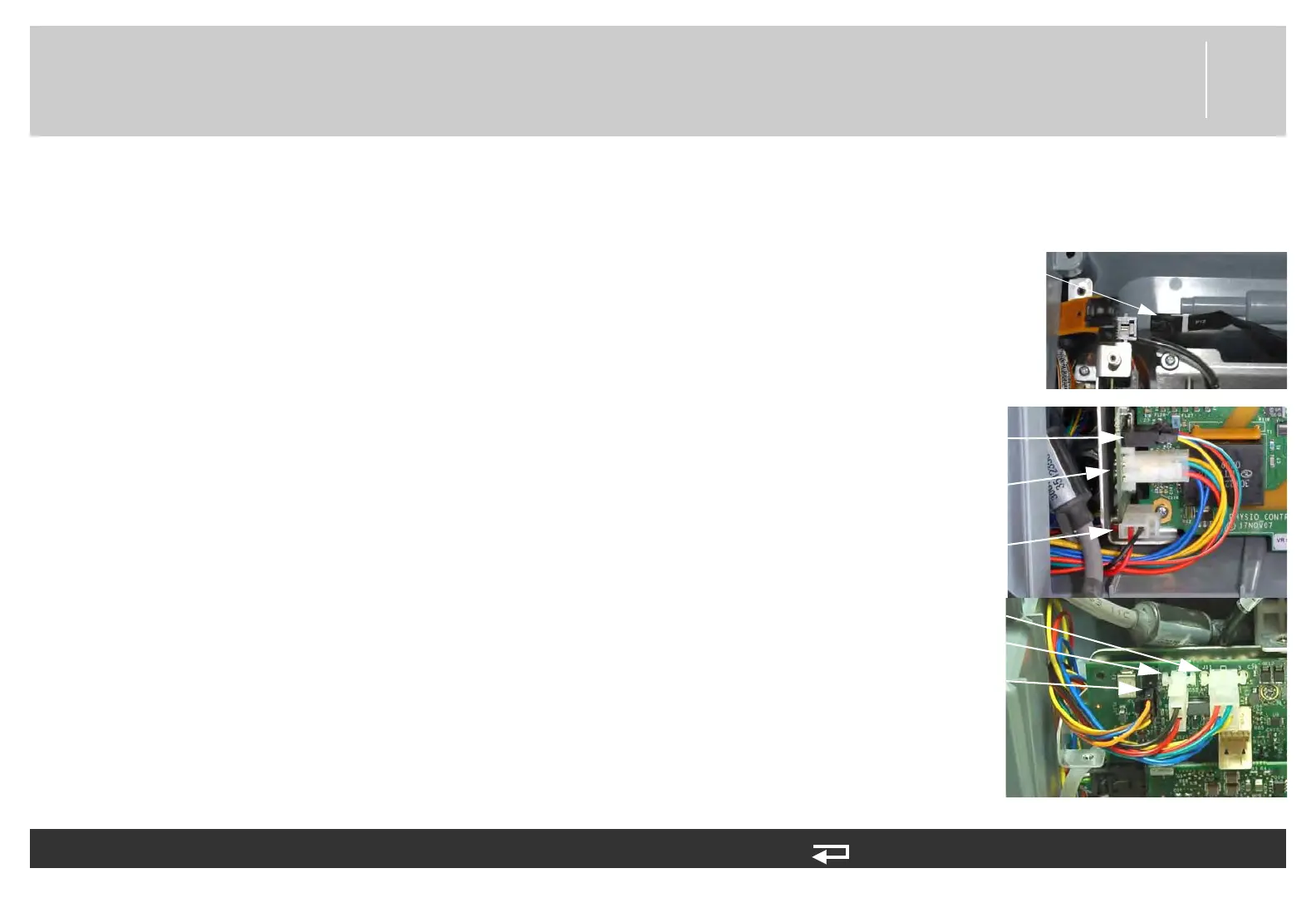
4. For V1 Power PCB (3206749-003): Disconnect the power/
contact (W05) at J12, battery pins/power PCB cable (W10) at
J11 and J13, and auxiliary power cable (W09) from the power
board at J15.
5. For V2 Power PCB (3302519-002): Disconnect the power/
contact (W05) at J12, battery pins/power PCB cable (W10) at
J11, and auxiliary power cable (W09) at J15-A and J15-B
from the Power PCB.
J13 connection
(W10)
J11 connection
(W10)
J15-A connection
(W09)
Figure 8.51—Power PCB
connections
J11 connection
(W10)
J15 connection
(W09)
J15-B connection
(W09)