LIFEPAK 15 Monitor/Defibrillator
Service Manual
Replacement Procedures
Power PCB (A03) Replacement
Section Menu Section Contents Procedures Back Index
255
8
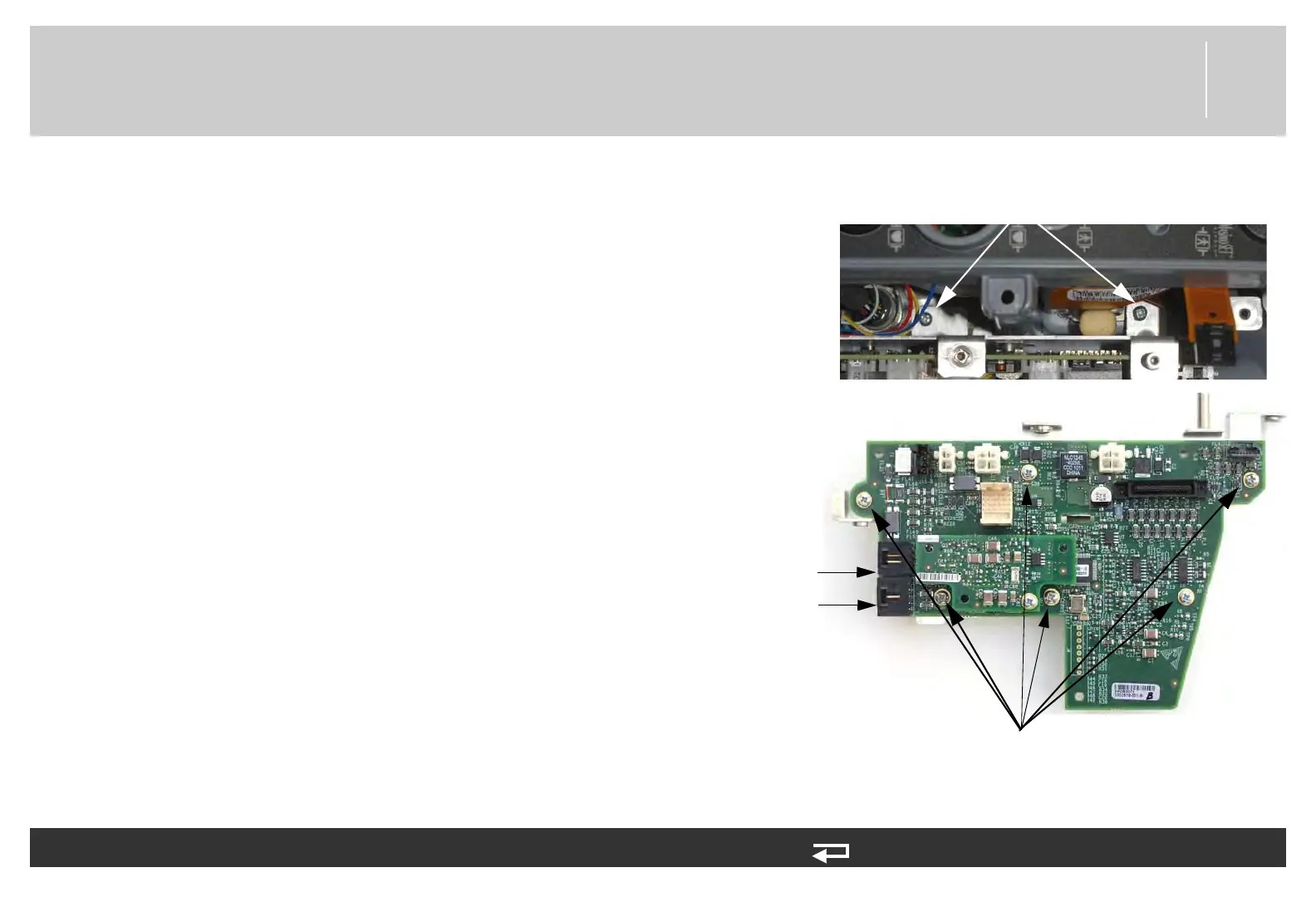
6. Remove the two screws (202253-761) securing the bracket
assembly (3206961-001). Discard the screws.
7. Lift the power PCB and bracket partially out of the rear case.
Use caution not to strain the system connector cable.
8. Disconnect the two W08 - system cable connectors at J9 and
J10 from the power PCB.
9. If you are replacing the power PCB, remove the six screws
(202253-761) securing the PCB to the mounting bracket
(3206961-001), and then remove the PCB. Discard the
screws.
To remove the power PCB (A03) from the rear case: (Continued) 10 steps, (Page 2 of 3)
mounting screws
(2 places)
(V2 pictured) screws mounting
PCB to bracket (6 places)
J10
connection
J9
connection
Figure 8.52—Power PCB
screw locations