LIFEPAK 15 Monitor/Defibrillator
Service Manual
Replacement Procedures
SpO2 PCB (A16) Replacement
Section Menu Section Contents Procedures Back Index
280
8
Installing the SpO2 PCB (A16)
NOTE: When installing a new SpO2 PCB, use the MASIMO Sp02 Module Repair Kit (MIN 3305431-025) (p. 513).
To install the SpO2 Module in the rear case (see Figure 9.21 on p. 413): 13 steps, (Page 1 of 4)
1. Install the SpO2 module (3207034-002) on the mounting
bracket.
2. Attach the SpO2 module to the bracket using four new screws
(202253-760); torque to 4.0 in-lb (see Figure 8.71 on p. 279).
3. Attach the SpO2/OEM flex cable (W21) to the SpO2 module
using one new screw (202253-760); torque to 4.0 in-lb.
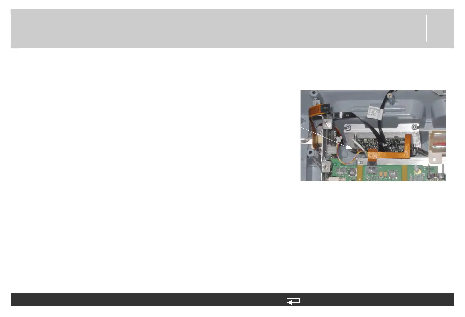
4. Connect the SpO2 connector flex cable (W22) (3206995-004)
to J1 of the SpO2 PCB.
NOTE: If installing the SpO2 connector flex cable
(W22), refer to SpO2 Connector Cable (W22)
Replacement (p. 344).
J1
connection
Figure 8.72—SpO2 PCB connection