User’s Manual of WGSW-20160HP/WGSW-24040HP series
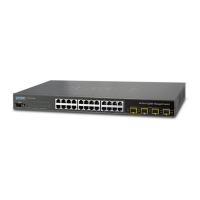
WGSW-24040HP series LED Indication Table
LED Definition
System
Lights to indicate that the Switch has power.
■ Alert
Lights to indicate the FAN1 failure.
Lights to indicate the FAN2 failure.
Lights to indicate the FAN3 failure. (For WGSW-24040HP4 only)
Lights to indicate the Power failure.
Per 10/100/1000Mbps port with PoE interfaces
LED Color Function
LNK/ACT Green
To indicate the link through that port is successfully established at
10/100/1000Mbps.
Blink: To indicate that the Switch is actively sending or receiving data over that port.
PoE In-Use Orange
Lights: To indicate the port is providing 56V DC in-line power.
Off: To indicate the connected device is not a PoE Powered Device (PD).
Per 100/1000Mbps SFP Combo Interface (Port -21 to Port-24)
LED Color Function
1000 LNK/ACT Green
To indicate the port is successfully established at 1000Mbps.
To indicate that the Switch is actively sending or receiving data over that port.
100 LNK/ACT Orange
To indicate the port is successfully established at 100Mbps.
To indicate that the Switch is actively sending or receiving data over that port.
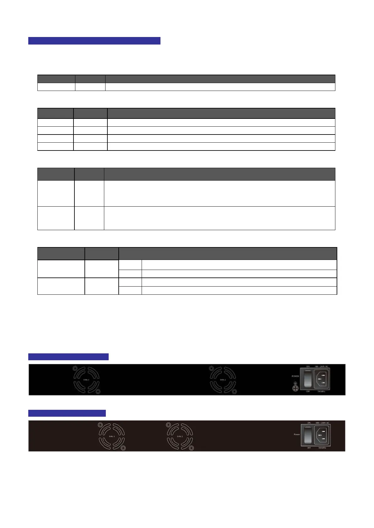
2.1.3 Switch Rear Panel
The rear panel of the Managed Switch indicates an AC inlet power socket, which accepts input power from 100 to 240V AC,
50-60Hz. Figure 2-3 shows the rear panel of the Managed Switch.
WGSW-20160HP Rear Panel
WGSW-24040HP Rear Panel
 Loading...