8
Manual No. 7018081-02, Rel. Jun. 1999
REMOVAL and INSTALLATION
© Copyright Isringhausen 1999
MODEL 6800/338 BUS
MODEL 6800/338 PREMIUM LX
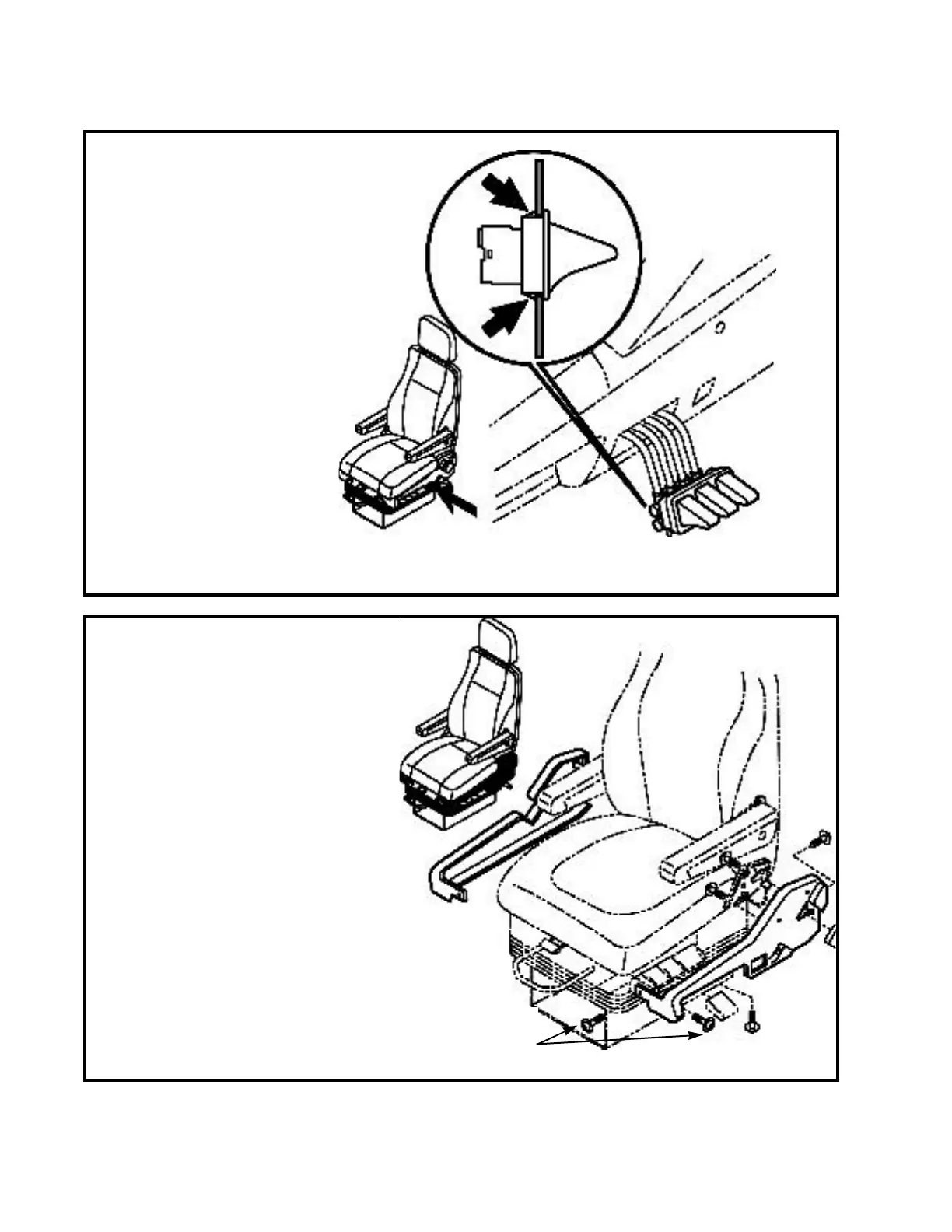
Lumbar and bolster valve
Set up
• Cover must be removed from seat
(see Covers front, LH and RH)
Removal
• Mark air line and remove them from
valve
• Press valve clips in and remove
valve from cover
Installation
• Snap valve into cover
• Connect air lines
Covers, LH and RH
Set up
• Vehicle must be in a safe parked position or
seat removed from vehicle.
Removal
Control cover
• Remove backrest adjustment handle
• Remove tilt adjustment handle - for fastener
access
• Remove fasteners and cover
Non control cover
• Remove fasteners and cover
Installation
Control cover
• Fasten cover to seat frame with screws
• Install backrest adjustment handle
• Install tilt adjustment handle - removed for
fastener access
Non control cover
• Fasten cover to seat frame with screws
torque to
5.3 - 8.8 lb in
(0.6 - 1.0 N•m)
do not over tighten