Page No.15
Manual No. NDS8
Spicer Speciality Axle Division - Technical Publications
© Spicer Speciality Axle Division
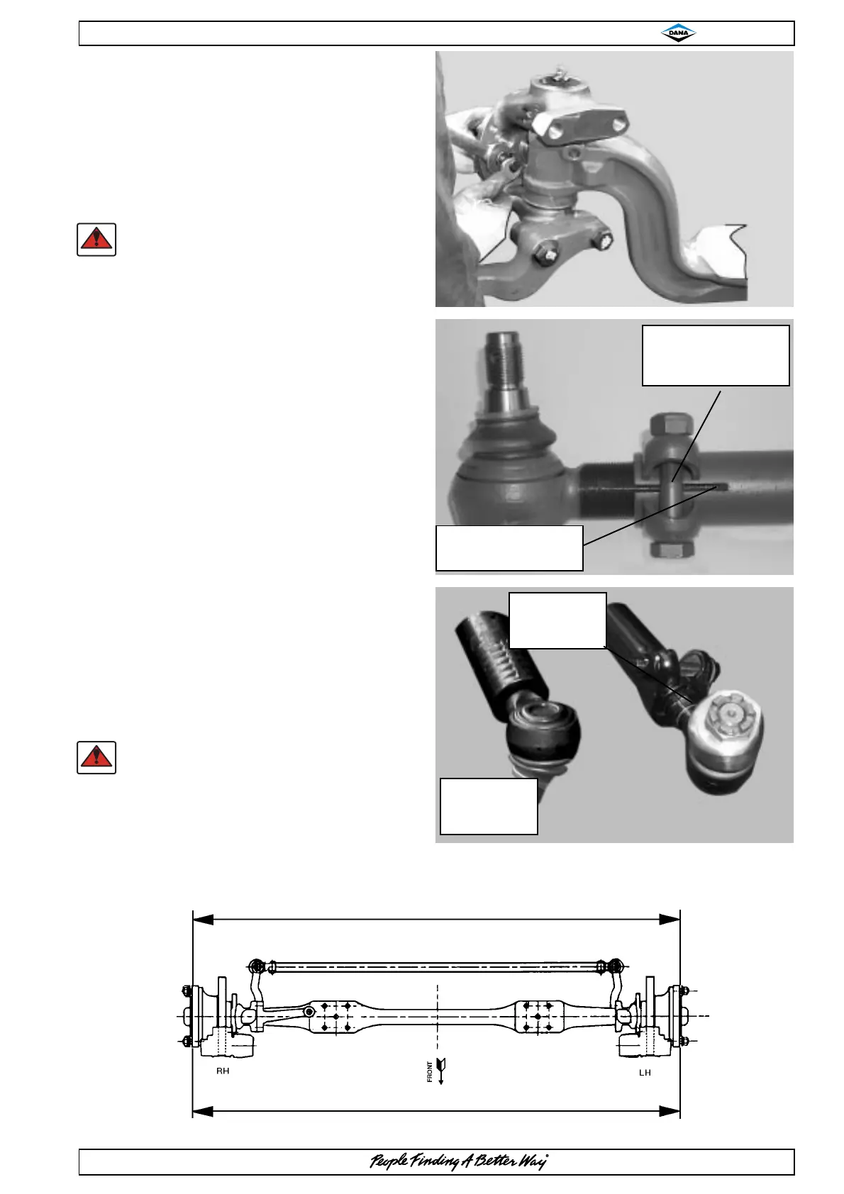
Clamp bolt
type A
Socket assembly
OVERHAUL PROCEDURES
HUB END REASSEMBLY CONTINUED
34. Refit lockstop screws and adjusting nuts
35. Reset lockstop screws to achieve correct
lock angles as shown on installation drawing
or vehicle manufacturers specifications.
NOTE:-
DO NOT ALLOW LOCKSTOP THREADS
TO PROTRUDE THROUGH FRONT FACE
OF SWIVEL.
36. Check wheel alignment as follows :-
a) Set axle in straight ahead position.
b) At a point level with wheel centre,
measure distance over hubs / wheel
rims, both in front and behind axle
centre.
c) Front measurement ‘B’ should be
0.0" to 0.04" (0.0 to 1mm) LESS
than rear measurement ‘A’.
d) Any adjustment on type A
socket and tie rod assemblies can
be effected by slackening clamp
bolts in ball sockets and rotating
track rod tube.
For type B socket and tie rod
assemblies, slacken the clamped
end of the assembly and use the
adjuster ring.
e) After adjustment, tighten clamp bolts
to specified torque.
NOTE:-
WHEN ADJUSTING TYPE A TIE RODS,
ENSURE SOCKET THREADS ARE
EQUALLY POSITIONED IN EACH END OF
THE TIE ROD AND THAT THE END OF
THE SOCKET THREAD IS NOT VISIBLE
THROUGH THE SAWCUT
'B'
'A'
Adjuster ring
type B Socket
assembly
End of threads must
not be visible here
Crimped end
type B Socket
assembly