2
5
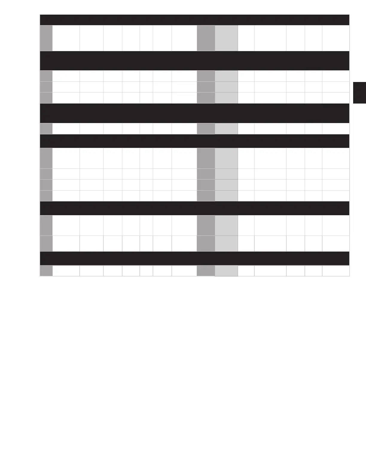
TUBELESS WHEELS (round hand holes) ENGLISH UNITS (METRIC UNITS)
Item
no.
Wheel descrip-
tion
Maximum
wheel load
1
in lbs.
(kilograms)
Approx.
Wheel
wt. lbs.
(kilo-
grams)
Outset
inches
3
(mm)
Inset
inches
(mm)
Maxi-
mum
ination
PSI—cold
(KPa)
Valve
stem***
(Alcoa Part
No.)
Part
number
2
Available
nishes
4
Stabi-
lizer
Front outer cap
nuts
Rear
inner
cap nuts
Al/Al
Rear in-
ner cap
nuts
Al/Stl
Rear outer cap
nuts
Eight-hole, hub piloted mounting—275mm bolt circle, 221.1mm hub bore, 24.75mm bolt hole diameter (use two-piece ange nuts) Lug nut
covers: 181 Hub covers: N/A Hub Cover Kits: 082122 (Front 33mm), 082133 (Rear 33mm), 082012 (30mm) 140233A (Stainless Front 33mm),
109176A (Stainless Rear 33mm)
31 17.5x6.75-15°DC 5515 (2500) 29.5 (13.4) 5.55 (141)
4.72
(120)
142 (978)
TR553C
(005533)
663470 0, 2 - 39874 - - 39874
32
19.5x6.75RW-
15°DC
5515 (2500) 36.4 (16.5) 5.55 (141)
4.72
(120)
142 (978)
TR553C
(005533)
764490 0, 1, 2 - 39874 - - 39874
33
19.5x7.50RW-
15°DC
6615 (3000) 37.7 (17.1) 6.10 (155)
5.28
(134)
142 (978)
TR553C
(005533)
773400 0**, 1, 2 - 39874 - - 39874
10-hole, hub piloted mounting—285.75mm bolt circle, 220.1mm hub bore, 26.75mm bolt hole diameter (use two-piece ange
nuts) Lug nut covers: 181 Hub covers: Front - 076018 or 076085‡ Rear - 077018 or 077085‡ One-Piece hub cover system: Front -
086100S, Rear - 087100
34
19.5x7.50RW-
15°DC
6615 (3000) 37.7 (17.1) 6.10 (155)
5.28
(134)
142 (978)
TR553C
(005533)
773600 0, 1, 2, 3 - 39874 - - -
10-hole, hub piloted mounting—335mm bolt circle, 281.2mm hub bore, 26.75mm bolt hole diameter (use two-piece ange-
nuts), Lug nut covers: 181 Hub covers: 5811 polished with view port for P/N 833580 only, all others: N/A
†35 22.5x8.25-15°DC 8047 (3650) 50.6 (23.0) 6.57 (167)
5.70
(145)
138 (952)
70MS7
(007007)
886520
0, 3, 0DB, 3DB,
0DF,
3DF, 0DD,
3DD
- 39874 - - 39874
†36 22.5x9.00-15°DC 9094 (4125) 51.5 (23.4) 6.89 (175)
6.02
(153)
142 (978)
70MS7
(007007)
896520
0, 3, 0DB, 3DB,
0DF, 3DF
- 39874 - - 39874
‡‡37
22.5x13.00-
15°DC
12,800 (5806) 76.0 (34.5) —
6.12
(155)
130 (896) TR553 (005530) 833580 0, 1 - 39874 - - 39874
38 24.5x8.25-15°DC 8500 (3855) 64.0 (29.0)
6.79
(172.5)
5.81
(147.5)
120 (827)
TR554D
(005544)
983500 0, 3 - 39874 - - 39874
Ten-hole, hub piloted mounting—335mm bolt circle, 281.2mm hub bore, 32.87mm bolt hole diameter (use two-piece ange -
nuts), Lug nut covers: N/A Hub covers: N/A
†39
22.5x8.25-15-
°DC (32mm bolt
hole)
8047 (3650) 50.3 (22.8) 6.57 (167)
5.70
(145)
138 (952)
70MS7
(007007)
886510
0, 3, 0DB, 3DB,
0DF,
3DF, 0DD,
3DD
- 4306.32 - - 4307.32
†40
22.5x9.00-15-
°DC (32mm bolt
hole)
9094 (4125) 51.2 (23.2) 6.89 (175)
6.02
(153)
142 (978)
70MS7
(007007)
896510
0, 3, 0DB, 3DB,
0DF, 3DF
- 4306.32 - - 4307.32
Six-hole, hub piloted mounting—205mm bolt circle, 160.2mm hub bore, 21.5mm bolt hole diameter (use two-piece ange nuts)
Lug nut covers: N/A Hub covers: N/A
41 17.5x6.00-15ºDC 4000 (1814)
27.0
(12.2)
5.0 (127)
4.25
(108)
130 (896) TR554C 664800 0,1 – – – – –
Do not exceed maximum wheel load. Customer must compare OEM vehicle load rating to maximum wheel load rating. Do not overinate. Refer to tire manufacturer’s
recommendation for proper tire pressure. Before mounting the tire, perform a wheel tment check to ensure proper clearance from any obstructions.
1 Capacity ratings as dual or single in highway service — bias-ply or radial. Load ratings in lbs. for items 31 through 41 rounded to nearest multiple of 5.
2 Part numbers listed for all sizes are brushed nish (the last digit of the six-digit numerical part number is “0”). Polished nishes are indicated by changing the “0”
with any of the suxes in the adjacent column (Available Finishes). Some wheels may bear part numbers not shown in this manual. Before servicing these wheels,
contact your Alcoa wheel representative for proper load, ination and part compatibility information.
3 Outset (positive)/inset (negative) — The distance from the rim centerline to the mounting face of the wheel. Inset (negative) places the rim centerline inboard of the
wheel mounting face and outset (positive) places the rim centerline outboard of the wheel mounting face (½ dual spacing = oset).
4 The Dura-Bright® surface treatment and the Dura-Flange® options are currently available together on the same wheel, indicated by the “DD” sux.
* Part numbers should end in “1” or “9” when used in an inset position and “0” or “2” when used in an outset position.
** This nish is only available under the non-stock policy.
*** TR55XX Valve stems are the standard rim valves with a rubber grommet. TR54XX are an acceptable option with “O” rings.
† Indicates European New Generation Wheels.
†† Check with vehicle manufacturer or axle manufacturer before retrotting to outset wide base wheels to ensure compatibility with axle and wheel end components.
P/Ns 841100, 841400, and 841600 are not recommended for use on “N” spindle trailer axles.
‡ Hub cover system kits P/N 076085 (front) and P/N 077085 (rear) contain screw-on Hug-a-lug® nut covers and require a minimum of four threads of the stud to
extend above the tightened cap nut for use.
‡‡ The minimum stud standout required for P/N 833580 is 2.375 inches (60.3mm) when using wheel nut P/N 39874. Taller nuts will require more stud standout.
§ P/Ns 885600 and 985600 are Alcoa Severe Service™ Wheels.
Dura-Bright® wheels with XBR™ Technology surface treatment option shine without polishing.
Just wash with soap and water, do not polish or clean with abrasives.
For more information call 800-242-9898 or visit www.alcoawheels.com/durabrightxbr.