Section 16: SUSPENSION
PA1562
20
3.13.3 Assembly
Execute assembly of the new joint parts in the
following sequence:
1. Complete moistening of the contact surface
between housing bore and ball pin through
application of the grease.
NOTE
Apply grease, only in the case of repair kit
(Prévost # 611114)).
2. Insert ball pin/bushing, assembly. In case of
the two-bolt type, ensure that the bolt bores
are in the correct position in relation to the
axis of the tube.
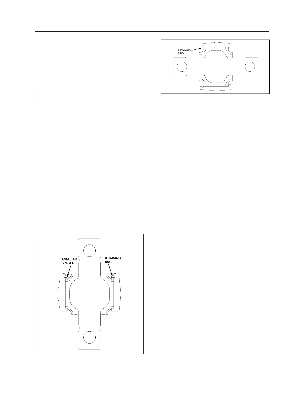
3. Place joint in receiving fixture and mount
annular assembly tool on the housing. Then
locate annular spacer and retaining ring in
the housing using axial load with the aid of
assembly matrix. If the ends of the annular
spacer are not in contact with each other,
the thus formed opening must be located at
180° to the opening of the retaining ring.
Pay attention during assembly to ensure
that the retaining ring eyelets are located at
each side of the housing shaft axis
(retaining ring eyelet lug points to tube), and
that retaining ring is properly engaged in the
groove of the housing.
4. When repairing defective ball pin
assemblies, the necked down-bolt must
regularly be replaced with a new one.
FIGURE 25: LOWER A-ARM BALL JOINTS 16114
FIGURE 26: UPPER A-ARM BALL JOINTS 16115
3.14 LOWER A- ARM CENTRAL BALL JOINT
3.14.1 Inspection
Take off the load from the ball joint by lifting the
front of the vehicle. Apply a load on the joint in
all of the degrees of freedom in an axial, radial,
etc. sense with a suitable lever tool. After the
load is taken off, the joint has to spring back into
its starting position. Free play is not acceptable
.
Separation of rubber from ball pin or external
joint bushing shell is in accordance with "normal
wear characteristics".
When the following characteristics are noted,
the joint is to be changed:
¾ Free play;
¾ Radial cracking of the external bushing
shell.
3.14.2 Stripping Down
Strip down the defective joint through removal of
retaining ring, annular spacer and ball
pin/bushing, assembly and thereafter clean out
housing bore and locking circlips groove.
3.14.3 Assembly
Assemble the new component parts of the joint
in the following sequence:
1. Complete moistening of the contact surface
between housing bore and ball pin through
application of the grease.
2. Place joint in receiving fixture and mount
annular assembly tool on the housing. Then
locate annular spacer and retaining ring in
the housing using axial load with the aid of
assembly matrix. If the ends of the annular
spacer are not in contact with each other,
the thus formed opening must be located at
180° to the opening of the retaining ring.
Pay attention during assembly to ensure
that the retaining ring eyelets are located at
each side of the housing shaft axis
(retaining ring eyelet lug points to tube), and
that retaining ring is properly engaged in the
groove of the housing.