Section 16: SUSPENSION
PA1562
21
3. Faultlessly apply grease by mechanical
means to bracket-outer core and ball-inner
cone. Insert bracket outer cone in fixture
with distance ring and then use press tool to
apply pressure to press mount with ball-
inner cone.
FIGURE 27: LOWER A-ARM CENTRAL BALL JOINT 16113
3.15 UPPER A-ARM CENTRAL BALL JOINT
3.15.1 Visual Inspection
Check the condition of the sealing boot, in
particular:
Check if the retainer ring, which secures the
sealing boot at the conical section of the ball
stud, is still present.
Check if grease is present on the external
surface of the sealing boots. Escaped fluid and
accumulations of grease on the sealing boot
may be the result of the sealing boot's rupturing.
In this case, the ball joint must be systematically
replaced.
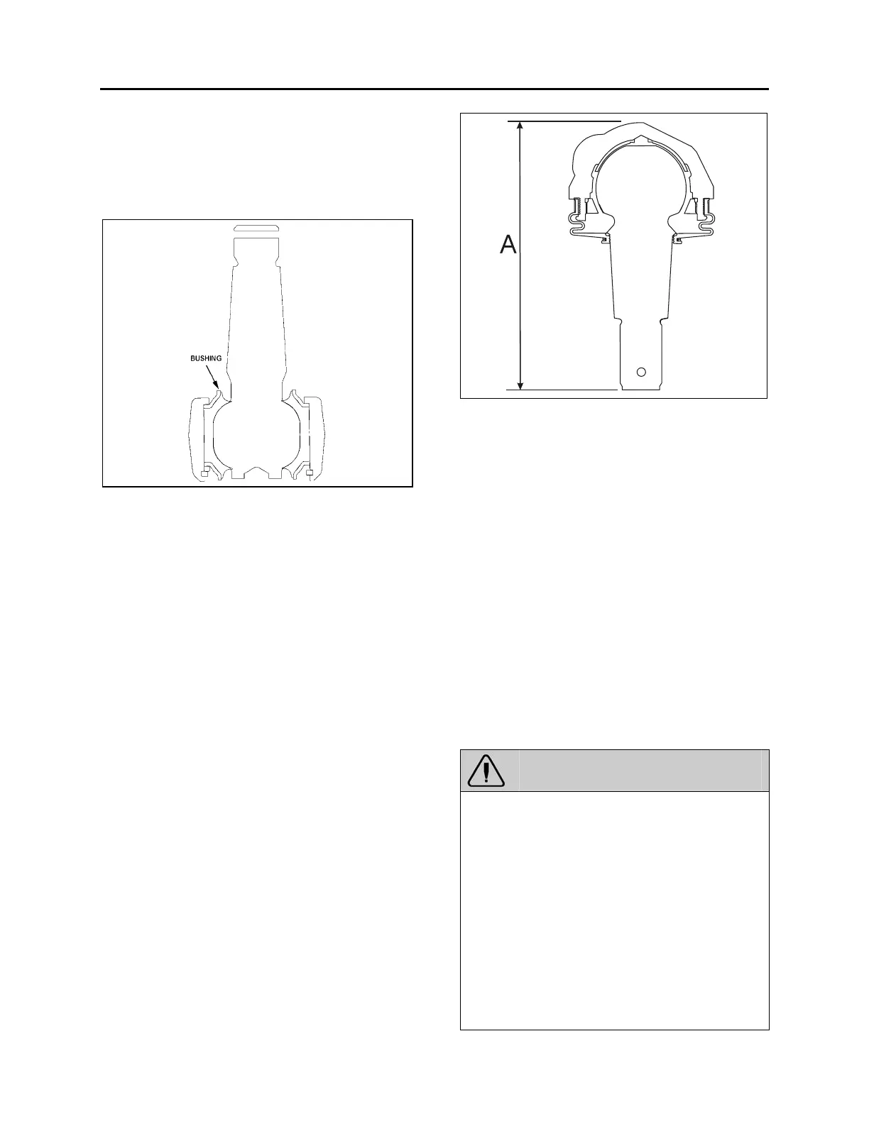
3.15.2 Play Measurement
1. Raise the vehicle and support through axle
jacking points.
2. Using a caliper, measure dimension A on
figure 28.
3. With a lever tool, exert sufficient force under
the upper A-arm as to separate the upper A-
arm from the upright in order to have the ball
joint to its maximum extent. Remeasure
dimension A. If the difference between the
two dimensions is greater than 0.060"
(1.5 mm), then the ball joint should be
replaced.
FIGURE 28: UPPER A-ARM CENTRAL BALL JOINT 16116
3.16 FRONT END ALIGNMENT
Proper front end alignment must be maintained
to insure ease of steering and provide
satisfactory tire life. When making front end
alignment inspections, the vehicle must be level
and empty with the full weight of the vehicle on
the wheels.
Front end alignment inspections fall into two
groups: regular service inspections performed at
periodic intervals, and inspections to determine
the extent of damage after a collision or severe
service.
Regular service inspections concern toe-in,
camber and caster.
Any variation from the specified alignment will
indicate either a need for adjustment or a more
thorough inspection to determine if parts
replacement is required.
WARNING
During alignment, both camber and caster
among other angles are adjusted. When
adjusting these we install or remove shims
from the lower “A” arms of the ISS
suspension. After performing alignment, make
sure that the following is done:
¾ Installing a new lock nut after all shims are
finalized.
¾ Torque replaced nuts as per figure 32.
¾ Installing a longer bolt if less the 2 threads
are remaining after the nut.
¾ Using a Torque mark on the nut for future
visual inspection.