7-26 Arranging the Components in the Control Cabinet Rexroth IndraDrive
DOK-INDRV*-SYSTEM*****-PR02-EN-P
Run the lines along grounded metal surfaces, in order to minimize
radiation of interference fields to area A (transmitting antenna effect).
Design and Installation in Strongly Interference-
Susceptible Area of Control Cabinet (Area C)
Area C mainly concerns the motor cables.
The discharge capacitance is limited to ensure compliance with the limit
values. The calculation of the discharge capacitance can be found in the
"Calculations" chapter.
If the applications allows this, the cable length should always be kept
short. Avoid unnecessary line lengths.
At the drive controller connection the motor cables and the (unfiltered)
power connection lines may only be routed in parallel for a distance of
300 mm. After that distance, motor cables and power supply cables have
to be routed in opposite directions in separate cables ducts, as illustrated
in the following figures (Fig. 7-22: Option 1: separate routing of motor
cable and mains connection lines via 2 cable ducts; Fig. 7-23: Option 2:
separate routing of motor cable and mains connection lines) by the
example of a drive system with separate mains connection per drive axis
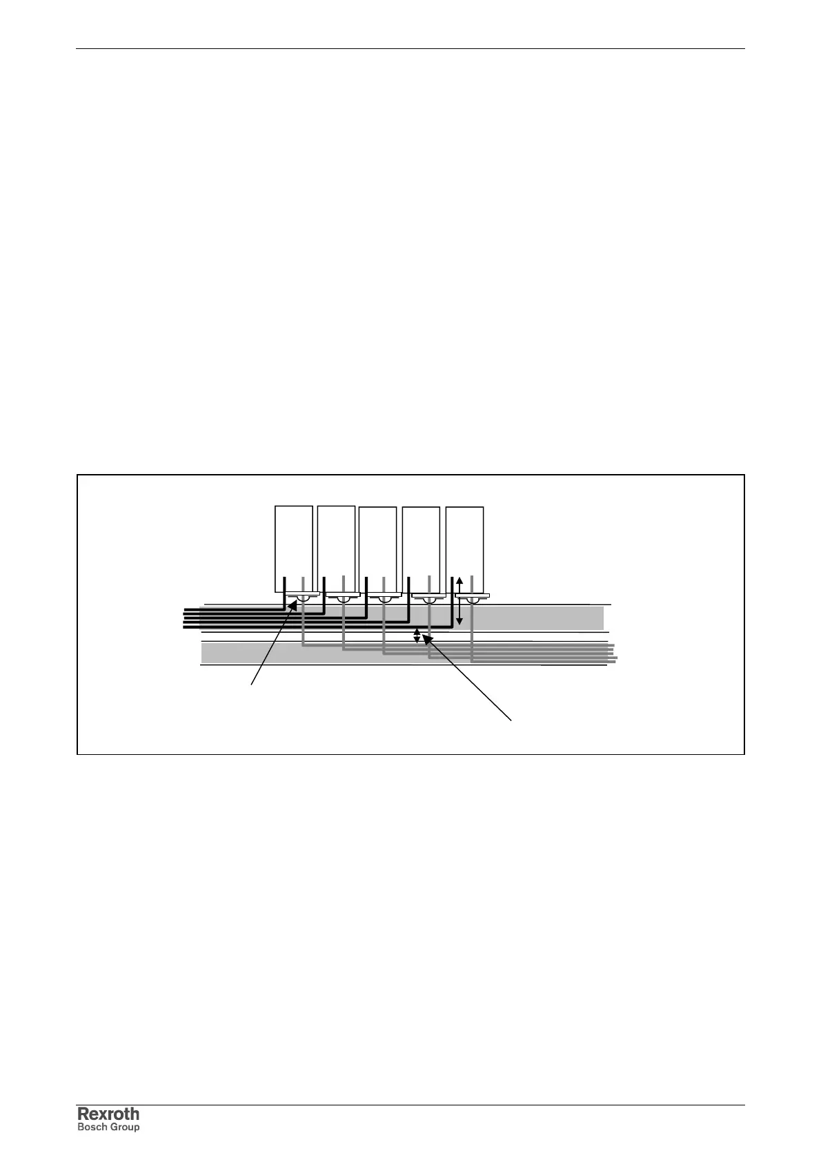
IndraDrive HCS.
cable duct 1:
mains connection
lines
cable duct 2:
motor cable
drive controllers
parallel routing:
length max. 300 mm
with a distance of at least 100 mm
or separated by grounded
distance plate
Area B Area C
motor cable:
shield contact via clips at least at one point:
alternatively at device or on mounting plate at
control cabinet outlet
Fig. 7-22: Option 1: separate routing of motor cable and mains connection lines
via 2 cable ducts
Line Routing
Influence of the Motor Power
Cable
Routing the Motor Cables