Rexroth IndraDrive Arranging the Components in the Control Cabinet 7-27
DOK-INDRV*-SYSTEM*****-PR02-EN-P
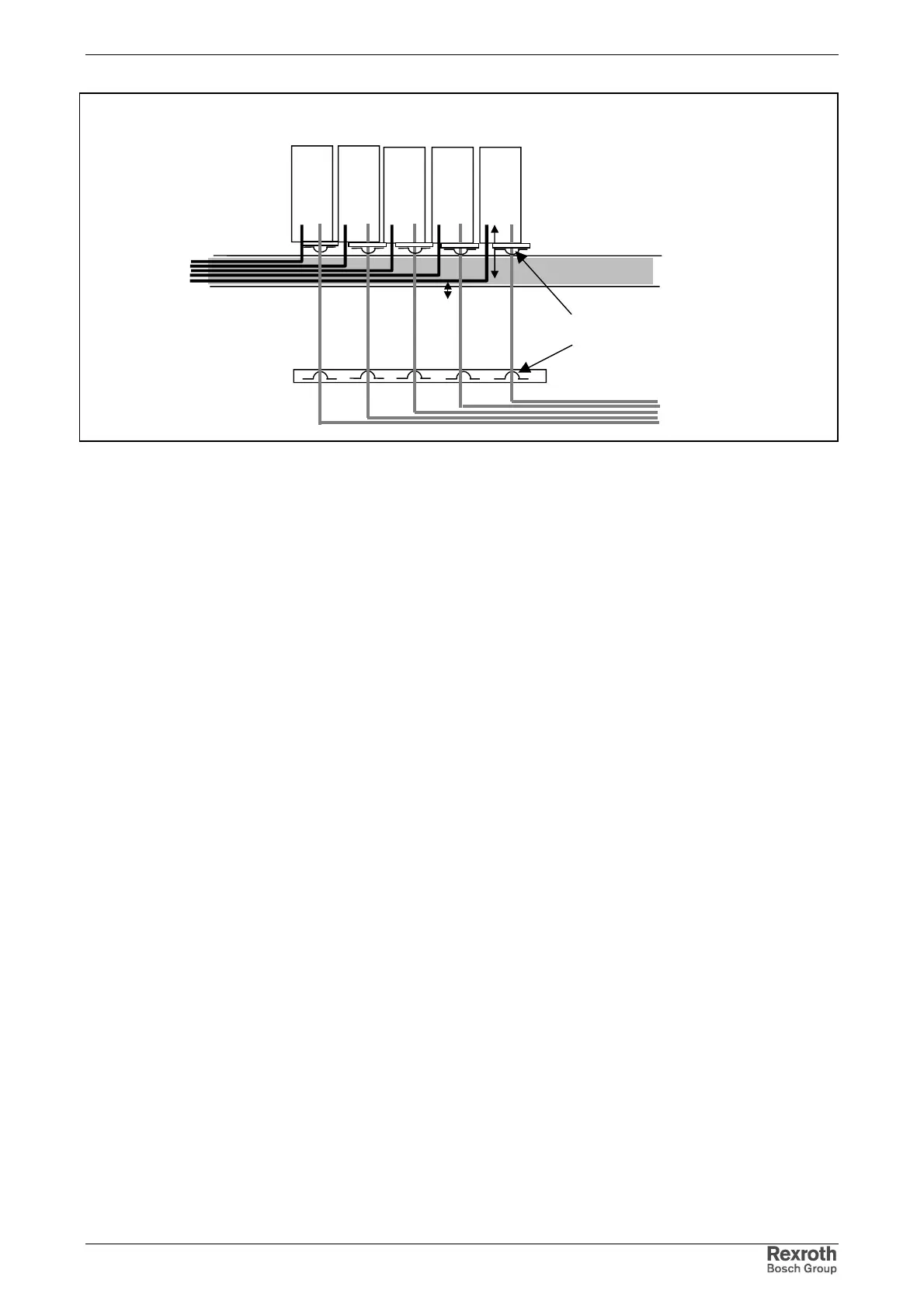
cable duct 1:
mains connection
lines
cable duct 2:
motor cable
drive controllers
parallel routing:
length max. 300 mm
Area B Area C
motor cable:
shield contact via clips at least at one
point: alternatively at device or on
mounting plate at control cabinet outlet
control cabinet outlet
motor cables
Fig. 7-23: Option 2: separate routing of motor cable and mains connection lines
The motor cables should be routed along grounded metal surfaces, both
inside the control cabinet and outside of it, in order to minimize radiation
of interference fields. If possible the motor cables should be routed in
metal-grounded cable ducts.
The outlet of the motor cables at the control cabinet should ideally be
provided in a distance of at least d3=400 mm from the (filtered) power
supply cable.
Additional Recommendations on
Cable Routing