Rexroth IndraDrive Calculations 15-3
DOK-INDRV*-SYSTEM*****-PR02-EN-P
DGmE.fh7
n
t
1
t
2
t
t
H
t
B
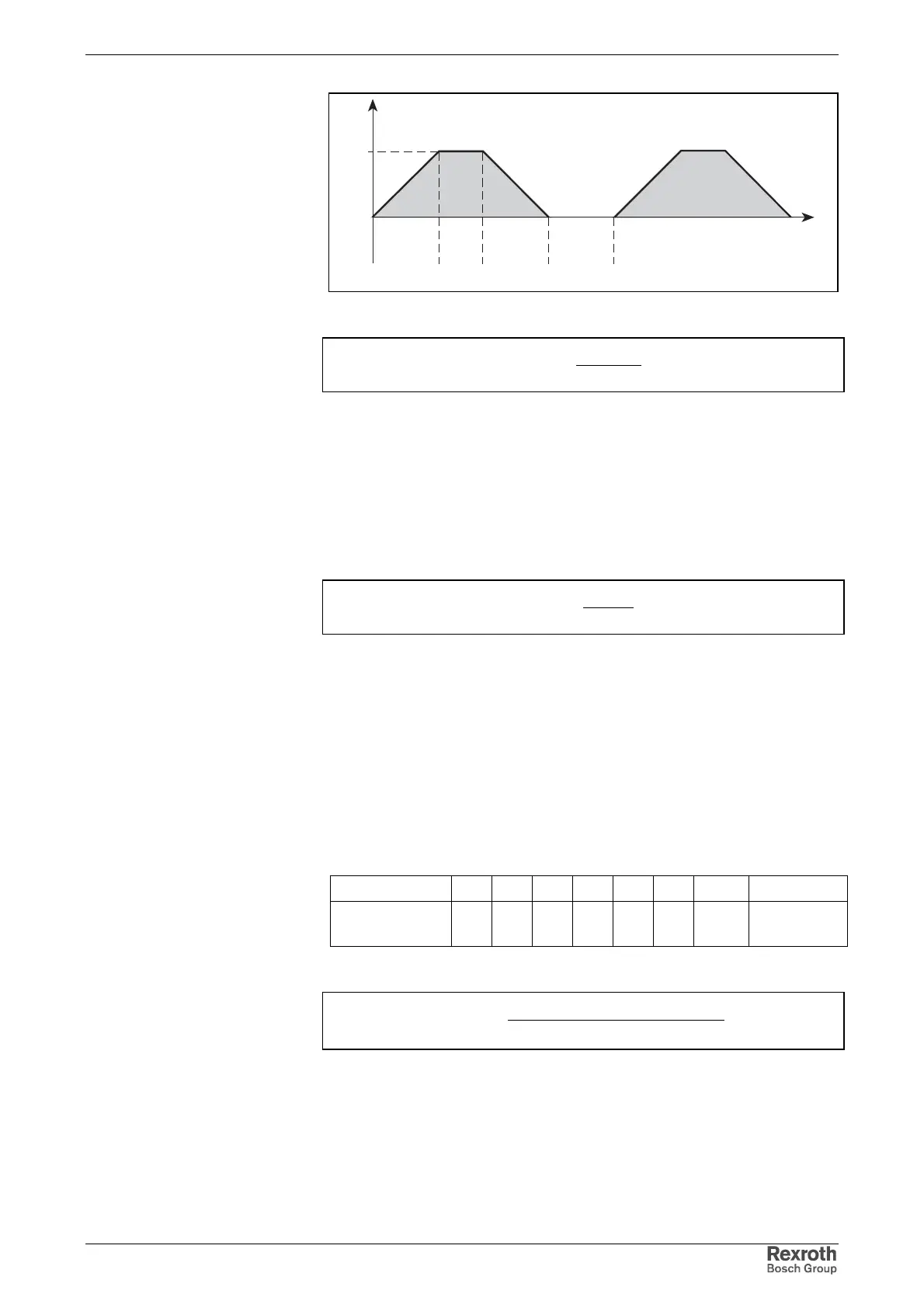
Fig. 15-5: Average speed; effects of run-up and braking times taken into account
9550
n*M
P
aveff
mSe
=
P
mSe
: mechanical continuous power for servo drives [kW]
M
eff
: effective motor torque [Nm]
n
av
: average motor speed [min
-1
]
Fig. 15-6: Mechanical power for servo drives
Main drives are drives which are mainly used in the constant power speed
range. Thus, nominal power is decisive for dimensioning the mains
supply. The mechanical nominal power of the main drives can be taken
from the operation characteristic or calculated from nominal speed and
nominal torque.
9550
n*M
P
nn
mHa
=
P
mHa
: mechanical nominal power for main drives (shaft output) [kW]
M
n
: nominal motor torque [Nm]
n
n
: nominal motor speed [min
-1
]
Fig. 15-7: Mechanical power for main drives
The drive controller or the combination of drive controllers has to make
available the DC bus power. However, in most applications, simultaneous
loading of all drives will not occur; thus, only the simultaneous load must
be considered for calculating the DC bus continuous power to be made
available for servo drives. To calculate the DC bus continuous power to
be made available for typical NC feed axes at machine tools, inclusion of
a so-called simultaneity factor has proved to be favorable in practical
application:
Number of axes
123456n=7 n=n+1
Simultaneity
factor (F
G
)
1 1,15 1,32 1,75 2,0 2,25 F
G
=2,5
F
Gn
=F
G
+0,25
Fig. 15-8: Simultaneity factors
G
mSenmSemSe
ZWDSe
F
,*)P...PP(
P
251
21
+++
=
P
ZWDSe
: DC bus continuous power for servo drives [kW]
P
mSe1
...P
mSen
: mechanical continuous power for servo drives [kW]
F
G
: simultaneity factor
1,25: constant for motor and controller efficiency
Fig. 15-9: DC bus continuous power for servo drives
Mechanical Power for Servo
Drives
Mechanical Power for Main
Drives
DC bus Continuous Power for
Servo Drives