Bosch Rexroth AG TS 2plus 4.27–8
40
400 N
7‑2
Clean
Room
11‑109 11‑78
4...6 bar
Positionieren und Orientieren · Positioning and orientation · Positionnement et orientation
3 842 531
138 (2013-06)
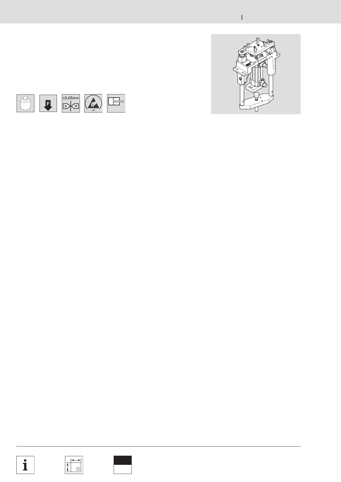
Hub‑Positioniereinheit HP 2/L
HP 2/L lift position unit
Unité de levée et de positionnement HP 2/L
Verwendung:
Positionierung eines Werkstückträgers
in einer Bearbeitungsstation mit hohen
Anforderungen an die Positionier‑
genauigkeit. Ab b = 240 mm
platzsparende Anordnung möglich durch
Anhalten des WT an der Innenseite.
Ausführung:
– Verwendbar mit Werkstückträgern
WT 2, WT 2/F, WT 2/E.
– Für b = 240 mm optional Hubzylinder
mittig (HA = 0) oder versetzt (HA = 1).
– Positionierung über wechselbare
Positionierstifte der HP 2/L
und Positionierbuchsen des
Werkstückträgers WT 2.
– Hubzylinder Ø 40 mm mit Dämpfung
der unteren und oberen Endlage.
– Wechsel des Hubzylinders ohne
Demontage der Hubplatte möglich.
– 5 Hubbereiche h
0
von 0–240 mm,
innerhalb des Hubbereichs stufenlos
zentral einstellbare Hubhöhe.
– Zulässige vertikale Prozesskraft bei
5 bar: bis zu 400 N (40 kg) incl. WT 2.
– Stellzeit auf/ab [s] bei H = 50
0.5/0.5 ohne Last
– Wiederholgenauigkeit in X‑ und
Y‑Richtung: ±0,04 mm für Hübe bis
204 mm.
Einbauort:
– unterhalb der Förderstrecke
(AO = UB)
– auf Maschinentischplatte (AO = AT)
– ohne Befestigungssatz (AO = O); bei
kundenspezifischer Lösung
Lieferumfang:
jeweils inklusive dem gewählten
Einbauort entsprechendem
Befestigungssatz und
Drosselrückschlagventil.
Lieferzustand:
montiert
Zubehör 7‑10.
Application:
For positioning a workpiece pallet in a
processing station that requires a high
degree of positioning accuracy.
From b = 240 mm, space‑saving
arrangement made possible by inner WT
stop.
Design:
– Can be used with WT 2, WT 2/F,
WT 2/E workpiece pallets.
– Optional lifting cylinder for
b = 240 mm, center (HA = 0) or
offset (HA = 1).
– Positioning with exchangeable
positioning pins in the HP 2/L and
positioning bushings in the WT 2
workpiece pallet.
– Lifting cylinder Ø 40 mm with damping
for the lower and upper end position.
– Exchange of lifting cylinder possible
without disassembling the lift plate.
– 5 lift ranges h
0
from 0–240 mm,
infinitely adjustable central lift height
within the lift range.
– Reliable vertical process force at
5 bar: up to 400 N (40 kg) incl. WT 2.
– Up/down adjustment time [s] at
H = 50, 0.5/0.5 without load
– Repetition accuracy in X and Y
directions: ±0.05 mm for lifts of up to
204 mm.
Mounting location:
– Under conveyor section (AO = UB)
– On machine table (AO = AT)
– Without mounting kit (AO = O); for
customized solutions
Scope of delivery:
Includes appropriate mounting kit and
throttle non‑return valve for the selected
mounting location.
Condition on delivery:
Assembled
Accessories 7‑10.
Utilisation :
Positionnement d'une palette porte‑
pièces à un poste de travail avec de
hautes exi gences en ce qui concerne la
précision du positionnement. À partir de
b = 240 mm, une disposition permettant
un gain de place est possible par arrêt
de la WT sur le côté intérieur.
Version :
– Utilisable avec palettes porte‑pièces
WT 2, WT 2/F, WT 2/E.
– Pour b = 240 mm, vérin de levée
central (HA = 0) ou en décalage
(HA = 1) en option.
– Positionnement de la HP 2/L et
des douilles de positionnement de
la palette porte‑pièces WT 2 avec
des goupilles de positionnement
échangeables.
– Vérin de levée Ø 40 mm avec
amortisse ment de la fin de course
supérieure et inférieure.
– Changement du vérin de levée sans
dé montage de la plaque de levage
possible.
– 5 plages de levée h
0
de 0–240 mm,
hauteur de levée au centre réglable
en continu à l'intérieur de la plage de
levée.
– Force de traitement verticale autorisée
à 5 bar : jusqu'à 400 N (40 kg), WT 2
comprise.
– Temps d'ajustage vers haut/bas [s]
pour H = 50, 0.5/0.5 sans charge
– Précision de répétition en abscisse et
en ordonnée : ±0,05 mm pour levée
jusqu'à 204 mm.
Emplacement de montage :
– Sous section de transport (AO = UB)
– Sur plateau de table de machine
(AO = AT)
– Sans jeu de pièces de fixation
(AO = O) ; solution adaptée aux
exigences client
Fourniture :
Jeu de pièces de fixation et limitateur de
débit unidirectionnel correspondant à
l‘emplacement de montage choisi inclus.
État à la livraison : Monté
Accessoires 7‑10.