1
2
3
4
5
6
7
8
9
10
11
12
13
14
15
16
17
Bosch Rexroth AGTS 2plus 4.2 11–125
00126849.eps
1L1 U1
U1
X1–1 X1–1
2L2 V1
V1
3L3 W1
W1
4TW1 TW1
5TW2 TW2
PEPE PE
PE
3
~
11
22
33
45
56
2
7 x 1,5 mm
PE PE
M
TW1
TW2
U1 1 1 L1
V1 2 2 L2
W1 3 3 L3
TW1 5 4 Thermo
TW2 6 5 Thermo
PE PE PE
Technische Daten · Technical Data · Données techniques
3 842 531
138 (2013-06)
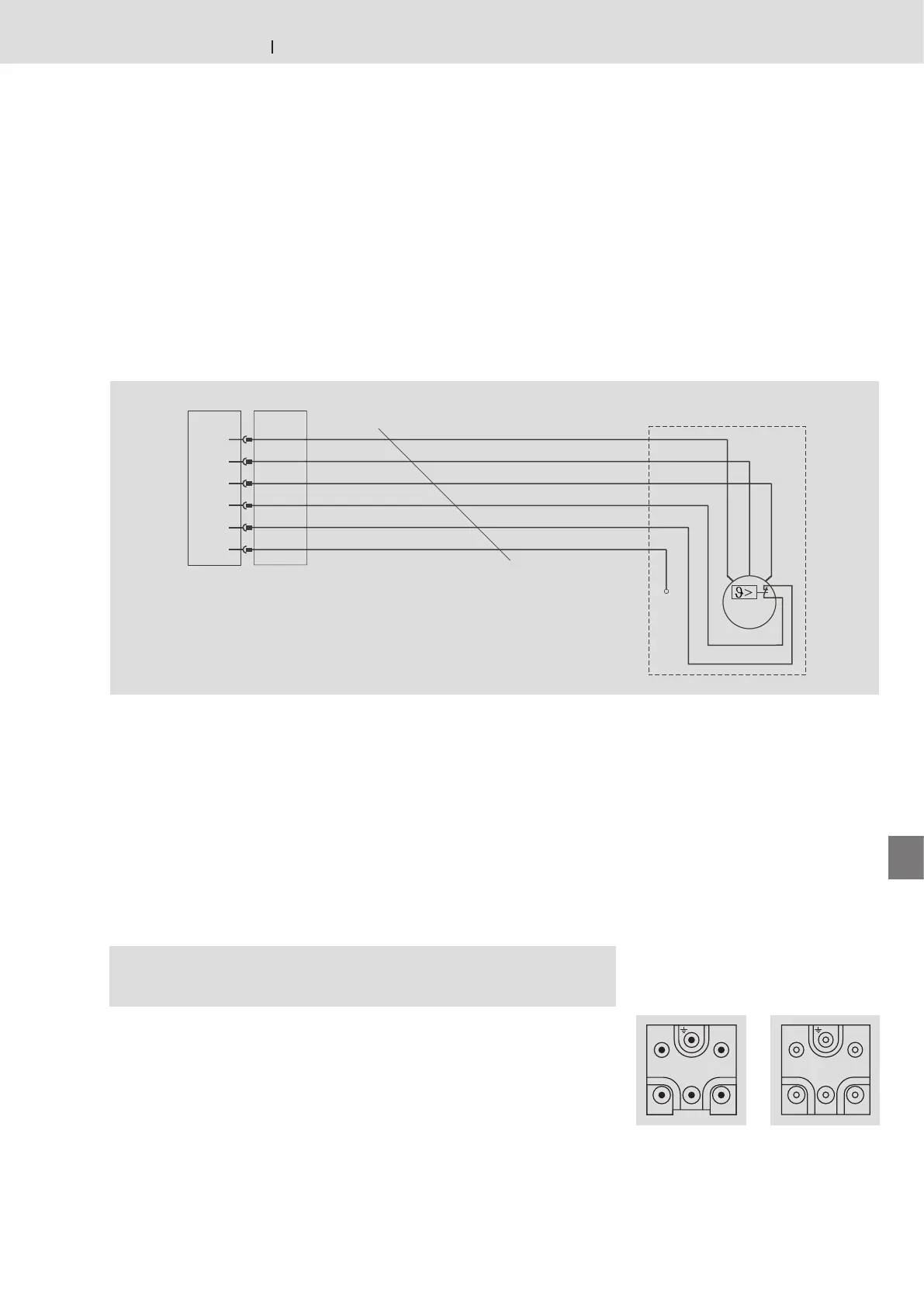
Motoranschluss
Motor connection
Raccordement du moteur
Anschlussklemmen Motor 3~ Ader-Nr Pin-Nr Code
Connection terminals, motor 3~ Wire no. Pin no. Code
Bornes de connexion, moteur 3~ N° de fil N° de broche Code
Verbindungsliste
Connector list
Liste des raccords
Stecker
Plug
Connecteur
Buchse
Bushing
Douille
Schaltplan
Circuit diagram
Schéma de connexions
Motoranschluss mit Kabel/Stecker (AT = S)
Motor connection with cable/plug (AT = S)
Raccordement du moteur avec câble/connecteur (AT = S)
Kabel nach VDE 0282 Teil 810,
z.B.:
– Lapp-Öl-Flex 7* x 1,5 mm
2
– HO7RN-F 7* x 1,5 mm
2
– YSLY-JZ 7* x 1,5 mm
2
* Ader-Nr. 4 ist abgeschnitten.
Cable according to VDE 0282 part 810,
e.g.:
– Lapp-Öl-Flex 7* x 1.5 mm
2
– HO7RN-F 7* x 1.5 mm
2
– YSLY-JZ 7* x 1.5 mm
2
* Wire no. 4 is cut off.
Câble suivant VDE 0282, partie 810,
par ex. :
– Lapp-Öl-Flex 7* x 1,5 mm
2
– HO7RN-F 7* x 1,5 mm
2
– YSLY-JZ 7* x 1,5 mm
2
* Le fil n° 4 est coupé.