Bosch Rexroth AG TS 2plus 4.27–12
00116128.eps
7‑2
Clean
Room
11‑109 11‑80
1100
N
4...6 bar
Positionieren und Orientieren · Positioning and orientation · Positionnement et orientation
3 842 531
138 (2013-06)
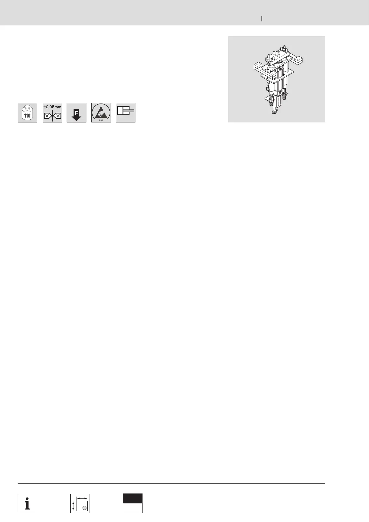
Hub‑Positioniereinheit HP 2
HP 2 lift position unit
Unité de levée et de positionnement HP 2
Verwendung:
Positionierung eines Werkstückträgers
in einer Bearbeitungsstation mit hohen
Anforderungen an die Positionier‑
genauigkeit.
Ausführung:
– Verwendbar mit Werkstückträgern
WT 2, WT 2/F, WT 2/E.
– Positionierung über die Positionier‑
stifte der HP 2 und Positionierbuchsen
des Werkstückträgers WT 2.
– Hubzylinder mit Dämpfung der unteren
und oberen Endlage (obere Endlagen‑
dämpfung nur bei voller Hubhöhe
wirksam).
– 8 Hubbereiche h
0
von 0–404 mm,
innerhalb des Hubbereichs stufenlos
einstellbare Hubhöhe.
– Zulässige vertikale Prozesskraft bei
5 bar: bis zu 1100 N incl. WT 2.
– Positioniergenauigkeit in X‑ und
Y‑Richtung: ±0,05 mm für Hübe bis
204 mm.
Einbauort:
Einfache Montage unter der
Förderstrecke (AO = UB) oder
auf der Maschinentischplatte einer
Bearbeitungsstation (AO = AT),
optional für Eigenkonstruktionen ohne
Befestigungsmaterial (AO = O).
Lieferumfang:
Je nach Einbauort inkl. Befestigungs‑
material zur Montage der HP 2
unter Förderstrecke oder auf der
Maschinentischplatte, Schalterhalter für
die Montage von Näherungsschaltern
M12x1 zur Stellungsabfrage der unteren
und oberen Hubstellung.
Lieferzustand:
Montiert
Zubehör 7‑14.
Application:
Positions a workpiece pallet in a
processing station with high positioning
accuracy requirements.
Design:
– Usable with WT 2, WT 2/F, WT 2/E
workpiece pallets.
– Positioning with the positioning pins
on the HP 2 and the positioning
bushings on the WT 2 workpiece
pallet.
– Lifting cylinder with damper at
the upper and lower end position
(damping at upper end takes effect
only under full lift).
– 8 lift ranges h
0
from 0–404 mm,
infinitely adjustable lift height within a
lift range.
– Permitted vertical process force at
5 bar: up to 1100 N incl. WT 2.
– Positioning accuracy in the direction of
the X and Y axes: ±0.05 mm for lifts of
up to 204 mm.
Mounting location:
Easy mounting under the conveyor
section (AO = UB) or on a table at a
processing station (AO = AT),
optionally available without fastening
material for individual designs (AO = O).
Scope of delivery:
Depending on the mounting position
incl. mounting material to install the
HP 2 under the conveyor section or on a
machine table, switch brackets to install
M12x1 proximity switches for position
indication at the upper and lower lift
positions.
Condition on delivery:
Assembled
Accessories 7‑14.
Utilisation :
Positionnement d’une palette porte‑
pièces dans un poste de traitement
avec des exigences de précision de
positionnement élevées.
Construction :
– Utilisable avec les palettes porte‑pièces
WT 2, WT 2/F, WT 2/E.
– Positionnement via les tiges de pos. de
la HP 2 et les douilles de positionnement
de la palette porte‑pièces WT 2.
– Vérin de levée avec amortissement en fin
de course sup. et inf. (amortissement en
fin de course supérieure effectif unique‑
ment pour une hauteur de levée entière).
– 8 plages de levée h
0
de 0–404 mm,
hauteur de levée réglable en continu
dans la plage de levée.
– Force de process verticale admissible à
5 bar : jusqu’à
1100 N
WT 2 incluse.
– Précision de positionnement dans les
directions X et Y : ±0,05 mm pour des
levées jusqu’à 204 mm.
Emplacement de montage :
Facile à monter sous la sec tion de
transport (AO = UB) ou sur le plateau
de table de machine d’un poste de
traitement (AO = AT), en option pour des
constructions propres sans matériel de
fixation (AO = O).
Fournitures :
Selon lieu d’implantation, matériel de
fi xation pour montage de la HP 2 sous
la sec tion de transport ou sur le plateau
de table, support d’interrupteur pour
montage des détecteurs de proximité
M12x1 pour détection de position de
levée inférieure et supérieure inclus.
Etat à la livraison :
Monté
Accessoires 7‑
14
.