GX-6000 Operator’s Manual Instrument Description • 10
Sensors
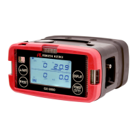
The GX-6000 uses five sensors to monitor combustible gas, oxygen (O
2
),
carbon monoxide (CO), hydrogen sulfide (H
2
S), and isobutylene (IBL)
simultaneously. The sensors are located inside the GX-6000 and are held in
their sockets by the flow chamber. The sensors use different detection
principles, as described below.
Combustible Gas Sensor
The % LEL sensor detects combustible gas in the % LEL range. It uses a
catalytic element for detection. The reaction of gas with oxygen on the
catalyst causes a change in the resistance of the element which affects the
current flowing through it. The current is amplified by the GX-6000’s
circuitry, converted to a measurement of combustible gas concentration, and
displayed on the LCD.
The standard calibration for the combustible gas sensor is to methane but the
sensor will still detect and respond to a variety of combustible gases.
Oxygen Sensor
The O
2
sensor is a galvanic type of sensor. A membrane covers the cell and
allows gas to diffuse into the cell at a rate proportional to the partial pressure
of oxygen. The oxygen reacts in the cell and produces a voltage proportional
to the concentration of oxygen. The voltage is measured by the GX-6000’s
circuitry, converted to a measurement of gas concentration, and displayed on
the LCD.
CO and H
2
S Sensors
The CO and H
2
S sensors are electrochemical cells that consist of two
precious metal electrodes in a dilute acid electrolyte. A gas permeable
membrane covers the sensor face and allows gas to diffuse into the
electrolyte. The gas reacts in the sensor and produces a current proportional
to the concentration of the target gas. The current is amplified by the GX-
6000’s circuitry, converted to a measurement of gas concentration, and
displayed on the LCD.
PID Sensor
Two types of PID sensors can be used with the GX-6000, a low range (higher
sensitivity) sensor and a high range (lower sensitivity) sensor (see Table 1 for
specifications).
The PID sensor is a cylindrical sensor with a diffusion opening on the front
and 3 pins on the back. It is installed in a white housing that has three sockets
on the bottom that mate with the GX-6000 instrument. The PID sensor must
always be installed in the first smart sensor position which is located in the

 Loading...