A2537-002/01 February 2020 2-8 SEMCO Proprietary Information
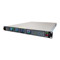
Figure 2-10 shows the 4 front panel LCD displays resulting from successful completion of steps 1 thru 9.
The 2 far left displays show CH1 and CH2 RF Tuner settings and a green Ch1 Synth Lock and Ch2 Synth
Lock indication.
The 3
rd
from the left display is the General Settings display, showing the main CH1, CH2 and Combiner
settings (Ch1, Ch2 and CMB) with respect to Frequency, Demodulation Format and Data Rate. The far-
right display provides General Status of CH1, CH2 and the Combiner channel.
Figure 2-10
Front Panel Display Settings Example
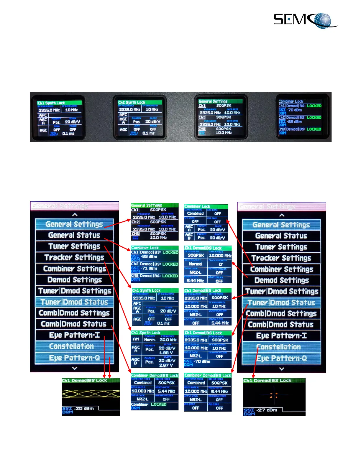
Figure 2-11 shows all available display selections available, with the corresponding screen display
associated with each selection. Steps 1 thru 9 above should be followed to select and position the desired
settings on each of the 4 front panel displays.
Figure 2-11
Front Panel Display Screen Settings