A2537-002/01 February 2020 3-1 SEMCO Proprietary Information
SECTION 3 – HARDWARE I/O
3.1 Hardware Telemetry I/O
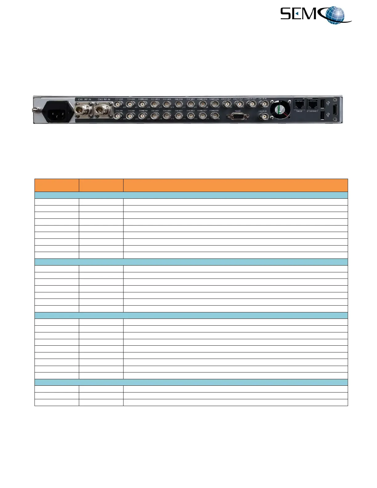
Figure 3-1 depicts the RC100C-2 Rear Panel Telemetry I/O outlined in red. The Reference Designators,
connectors and a brief description is provided in Table 3-1.
Figure 3-1
RC100C-2 Rear Panel Telemetry I/O
Table 3-1
RC100C-2 System I/O
CH1 RF IN; 50 Ohm impedance
CH1 IF In (70 MHz IF Input & recorded pre-d 70 MHz playback; 50 Ohm Impedance)
CH1 IF OUT (70 MHz IF Output; 50 Ohm Impedance)
CH1 VID 0 (0-4 VDC Analog Baseband Video Output; 75 Ohm impedance)
CH1 VID 1 (0-4 VDC Analog Baseband Video Output; 75 Ohm Impedance)
CH1 VID 2 (Digital TTL Clock Output; 75 Ohm Impedance)
CH1 VID 3 (Digital TTL Data Output; 75 Ohm Impedance)
CH1 AM (AM Output; 2.0 Vp-p @ 50% AM; selectable 50 or 75 Ohm impedance)
CH1 AGC (AGC Output; scalable +/-10, 20 or 50 dB/V; selectable HI-LO impedance)
COMB AGC (AGC Output; +/-10, 20 or 50 dB/V; selectable HI-LO impedance)
COMB AM (AM Output; 2.0 Vp-p @ 50% AM; selectable 50 or 75 Ohm impedance)
COMB VID 0 (0-4 VDC Analog Baseband Video Output; 75 Ohm impedance)
COMB VID 1 (0-4 VDC Analog Baseband Video Output; 75 Ohm impedance)
COMB VID 2 (Digital TTL Clock Output; 75 Ohm Impedance)
COMB VID 3 (Digital TTL Data Output; 75 Ohm Impedance)
COMB IF OUT (70 MHz IF Output; 50 Ohm Impedance)
CH2 RF IN; 50 Ohm impedance
CH2 IF In (70 MHz IF Input & recorded pre-d 70 MHz playback; 50 Ohm Impedance)
CH2 IF OUT (70 MHz IF Output; 50 Ohm Impedance)
CH2 VID 0 (0-4 VDC Analog Baseband Video Output; 75 Ohm impedance)
CH2 VID 1 (0-4 VDC Analog Baseband Video Output; 75 Ohm Impedance)
CH2 VID 2 (Digital TTL Clock Output; 75 Ohm Impedance)
CH2 VID 3 (Digital TTL Data Output; 75 Ohm Impedance)
CH2 AM (AM Output; 2.0 Vp-p @ 50% AM; selectable 50 or 75 Ohm impedance)
CH2 AGC (AGC Output; scalable +/-10, 20 or 50 dB/V; selectable HI-LO impedance)
Optional Bit Sync, Frame Sync & BERT RS422 and CMOS /TTL I/O
Remote (network) Control via Ethernet
3-Channel CH10 or IRIG 218 Telemetry Over IP