A2537-002/01 February 2020 6-7 SEMCO Proprietary Information
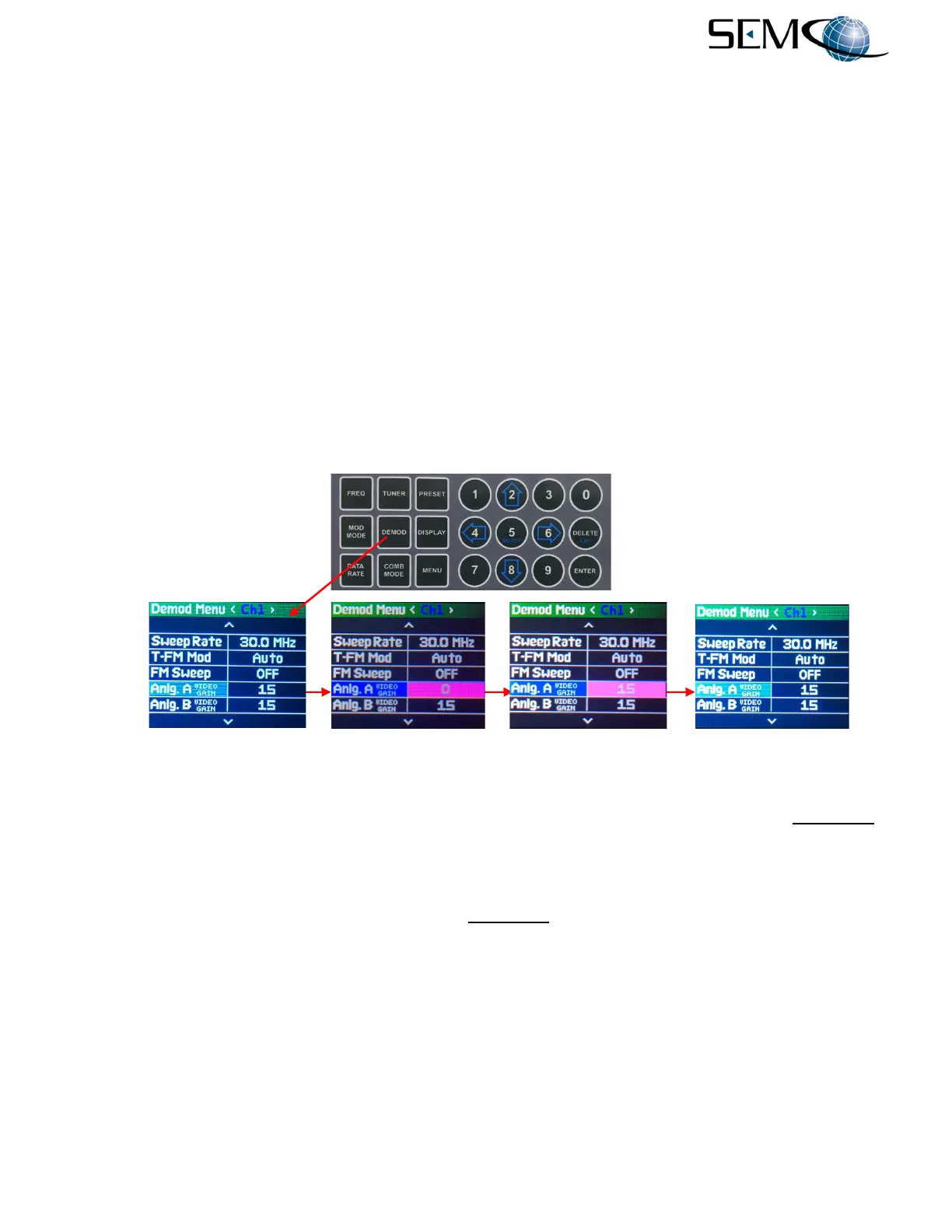
Figure 6-12 illustrates the steps for setting the analog baseband video gain of each demodulator. This
video gain is expressed in a selectable 0 to 15 dB range.
The operator pushes the DEMOD MODE button to access the Demod Menu display, uses the UP (2) and
DOWN (8) arrows to scroll to Anlg. A Video Gain in blue, and then pushes ENTER or SELECT (5) to
highlight the Anlg. A Video Gain selection window in bright magenta. The operator then uses the
numerical keypad to enter the desired Analog Video A Gain value (0 to 15 dB) and pushes ENTER or
Select (5).
Using the horizontal LEFT (4) and RIGHT (6) arrows, the operator selects <Ch2> and <Comb> in the
Demod Menu header display bar. The operator then pushes ENTER or SELECT (5) to highlight the Anlg.
A Video Gain selection window in bright magenta, uses the numerical keypad to enter the desired
Analog Video A Gain value (0 to 15 dB) and pushes ENTER or Select (5).
The operator repeats these steps for Analog B Video Gain (Anlg. B Video Gain) for SOQPSK, QPSK,
AQPSK and AUQPSK demodulator formats (analog I and Q outputs).
As previously mentioned, the Analog A and Analog B Gain values only need to be entered once for all 3
channels if Diversity Slaving is enabled.
Figure 6-12
Front Panel Analog Video Gain Selection
Figure 6-13 shows how to select Baseband Video FIR Filter values using the remote GUI. Video BW
displays the Video FIR filter bandwidth, and 15 selectable FIR Filter values are made available to the user
for every demodulator and data rate selected.
Two Video Filter bandwidths are displayed for QPSK, A/U/QPSK and SOQPSK analog I and Q baseband
video outputs. The user clicks on the arrow under Video BW to select any of the 15 available FIR filter
values in the pull-down menu as shown.
As previously mentioned, the optimum Video FIR BW value for all demodulation formats with I and Q
outputs is generally determined by 0.7 x (Data Rate/2). All other Video FIR BW values are normally 0.7 x
Data Rate.
A Vp-p slide bar that can be adjusted using the mouse is also provided as shown to adjust the gain of
analog base-band video outputs from 0 to >4 Vp-p into 75 ohms. The slide bar is expressed as a 0 to 15
dB readout. Two slide bars are displayed for QPSK, A/U/QPSK and SOQPSK analog I and Q baseband
video outputs.