A2537-002/01 February 2020 2-9 SEMCO Proprietary Information
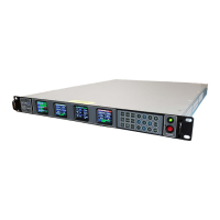
As previously shown in Steps 2 and 3 above, there are cases where there are multiple choices, such as
which Tuner or Demod to display, and a pop-up will appear after pressing ENTER for choosing between
CH1, CH2 and/or Combiner. The operator then uses the UP (2) and DOWN (8) arrows to highlight the
desired selection and press ENTER. Figure 2-12 provides examples of screens with multiple choices.
Figure 2-12
Front Panel Display Settings with Multiple Choice Selection
2.4.3 STATUS Lock/Unlock Indicators
Status LOCK and UNLOCK indicators are provided on the front panel displays for the RF Synthesizer
(Tuner), Combiner, Demodulator and Bit Synchronizer Demodulator.
A. Top bar in Tuner Status displays is GREEN for Synthesizer LOCK and RED for UNLOCK.
B. Top Bar in Combiner Status displays is GREEN for Combiner LOCK and RED for UNLOCK.
C. Top Bar in Demod Status displays is GREEN for Demodulator and Bit Synchronizer LOCK, YELLOW
with Demodulator only LOCK, and RED for UNLOCK.
2.5 Initial SLTS Remote Network Setup
Figure 2-13 shows Client and RC100C-2 network connections. The RC100C-2 has 2 RJ45 Ethernet
connections on the rear panel and network control is labeled LAN. Client OS is Win 7/10.
Figure 2-13
Client and RC100C-2 Network Connections
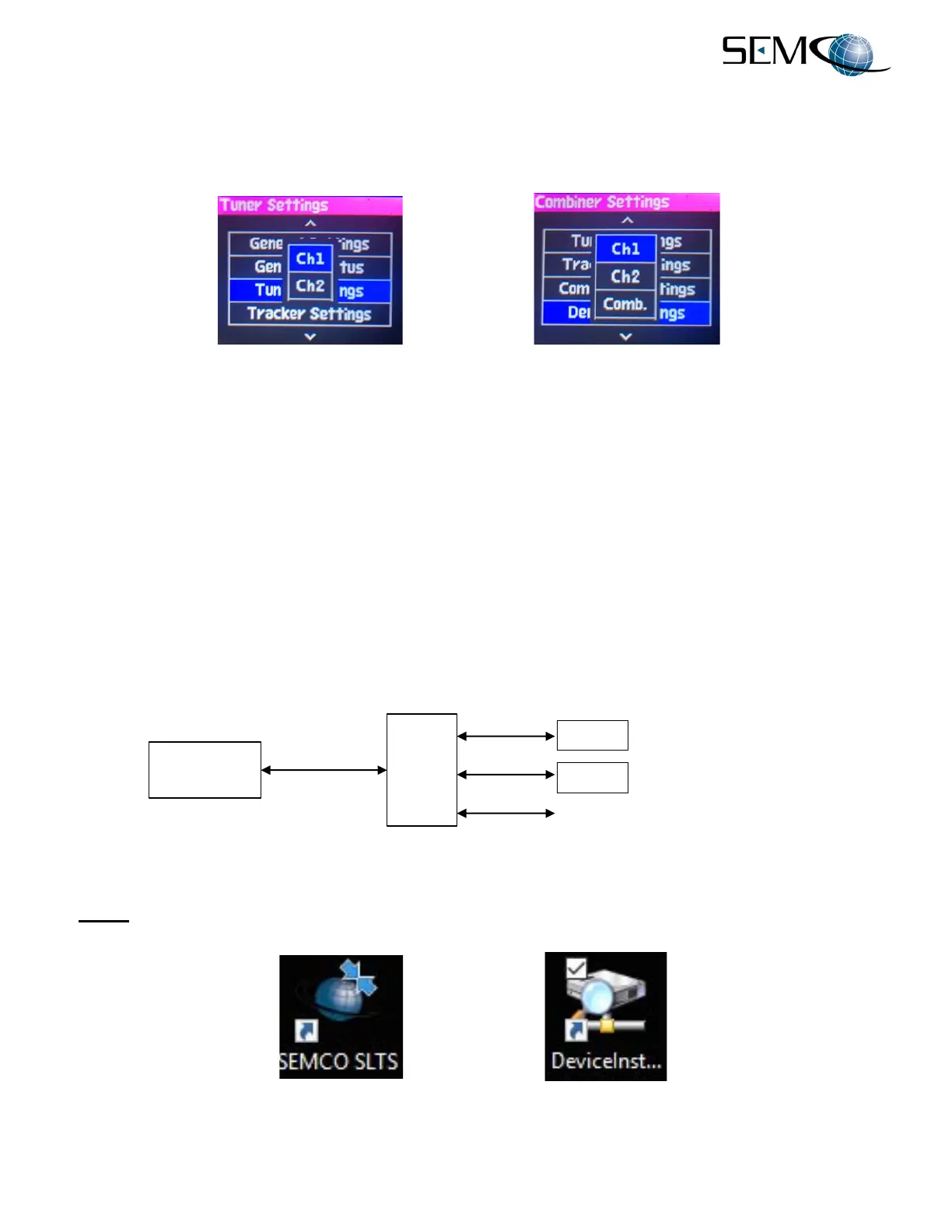
Step 1 - Install the SLTS and Lantronix software application on the Client. The SEMCO SLTS and Lantronix
Device Installer icons appear on the Client Desktop as shown in Figure 2-14.
Figure 2-14
Client SLTS and Lantronix Desktop Icons
…Additional RC100C Receivers as required