A2537-002/01 February 2020 4-4 SEMCO Proprietary Information
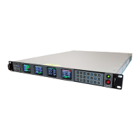
Clicking on the remote GUI CIF Enabled box just below the Input Freq (MHz) window enables the CIF
Mode (Figure 4-7) and re-inverts the spectrum to normal when a CIF-Band frequency is selected.
Figure 4-7
Entering a CIF-Band Frequency on Remote GUI
4.2 Receiver Signal Strength Indicator (RSSI)
4.2.1 Front Panel Absolute RSSI Display
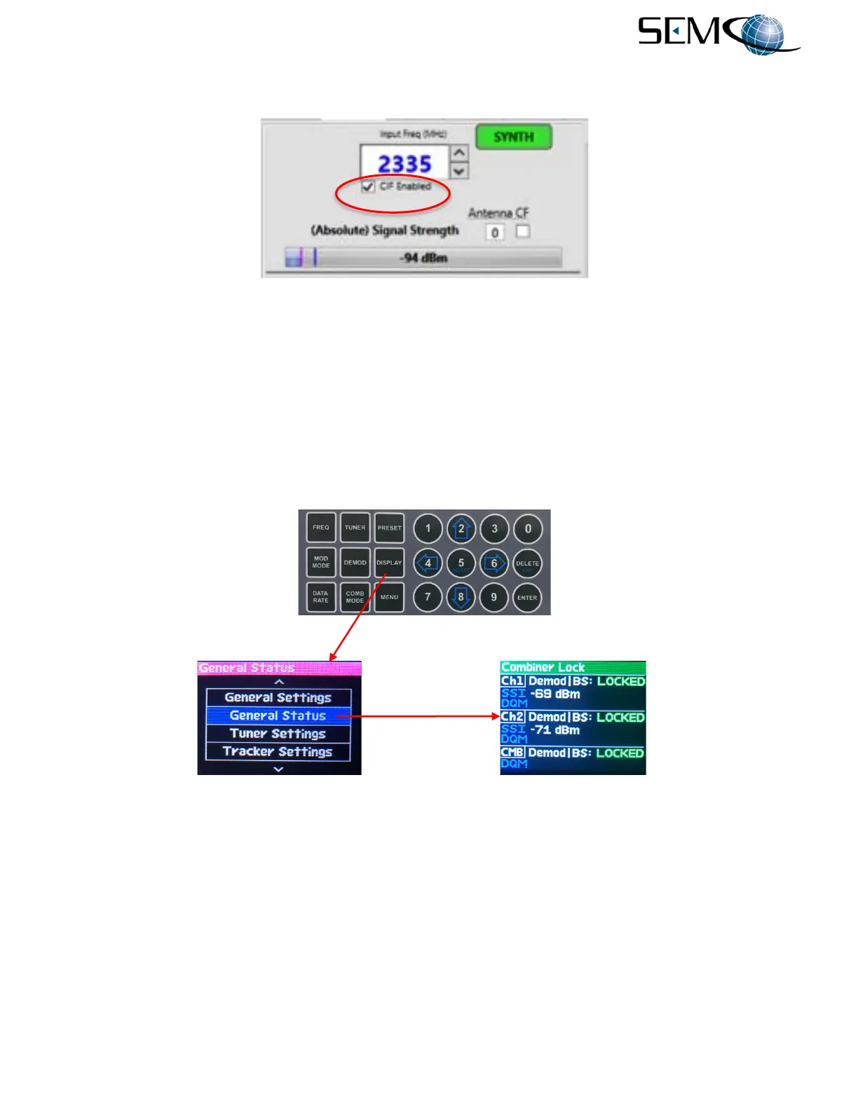
Selecting a front panel display that indicates an Absolute RSSI indication is shown in Figure 4-8. The
operator pushes DISPLAY and then the UP (2) and DOWN (8) arrows until GENERAL STATUS is
highlighted in blue. The operator then pushes ENTER or SELECT (5) to enable the GENERAL STATUS
display and an Absolute RSSI (SSI) as shown.
Figure 4-8
Absolute RSSI Status Display
4.2.2 Front Panel Relative RSSI Display
The Relative RSSI feature provides the ability to “zero” the RSSI reading, which then indicates the positive
or negative RF signal strength “relative” to this zero indication. This feature is usually enabled at the noise
floor prior to receiving an incoming RF signal, and provides a very accurate means to measure the
incoming RF signal.
Figure 4-9 illustrates the Relative RSSI feature. The operator pushes the TUNER button, uses the UP (2)
and DOWN (8) arrows to highlight AGC Zero in blue as shown, pushes ENTER or Select to highlight
OFF/ON in bright magenta, pushes either the UP (2) or DOWN (8) arrows to select ON, and then pushes
ENTER or SELECT (5) to turn <Ch1> AGC Zero ON.