A2537-002/01 February 2020 4-13 SEMCO Proprietary Information
4.5 AGC Settings
AGC Slope, polarity and impedance settings for all 3 receiver channels (CH1, CH2 and Combiner Channel)
includes AGC Slope and Polarity, Output Impedance, AGC Zero, AGC Freeze and AGC Time Constant
values. Steps for selecting each parameter is described in the following paragraphs.
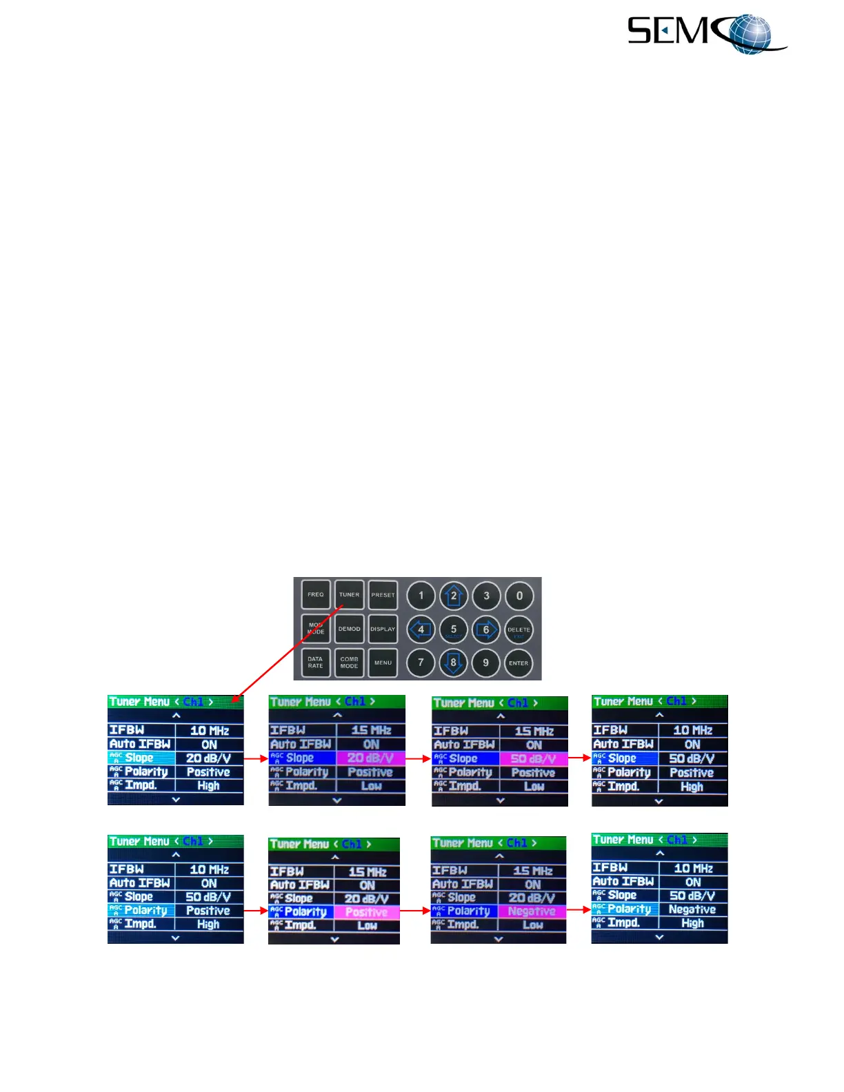
4.5.1 Front Panel AGC Slope and Polarity Selection
Referring to Figure 4-20 for AGC Slope selection, the operator pushes the TUNER button, uses the UP (2)
and DOWN (8) arrows to scroll to AGC Slope in blue, and then pushes ENTER or SELECT (5) to highlight
the AGC Slope value window in bright magenta. Using the UP (2) and DOWN (8) arrows, the operator
then selects the AGC Slope value (10 dB/V, 20 dB/V or 50 dB/V) and pushes ENTER or SELECT (5) for
<Ch1> AGC Slope value.
Using the horizontal LEFT (4) and RIGHT (6) arrows, the operator selects the other receiver channel,
pushes ENTER or SELECT (5) to highlight the AGC Slope window in bright magenta, uses the UP (2)
and DOWN (8) arrows to select the desired Slope and pushes ENTER or SELECT (5). For the Combiner
channel, the operator pushes the COMB MODE button and repeats the process.
Referring again to Figure 4-20 for AGC Polarity selection, the operator pushes the TUNER button, uses
the UP (2) and DOWN (8) arrows to scroll to AGC Polarity in blue, and then pushes ENTER or SELECT
(5) to highlight the AGC Polarity window in bright magenta. The operator then uses the UP (2) and
DOWN (8) arrows to select Positive or Negative and pushes ENTER or SELECT (5) for AGC Polarity.
Using the horizontal LEFT (4) and RIGHT (6) arrows, the operator selects the other receiver channel,
pushes ENTER or SELECT (5) to highlight the AGC Polarity window in bright magenta, uses the UP (2)
and DOWN (8) arrows to select the desired Polarity and pushes ENTER or SELECT (5). For the Combiner
channel, the operator pushes the COMB MODE button and repeats the process.
Figure 4-20
AGC Slope and Polarity Selection Using Front Panel
-------------------------------------------------------AGC Slope Selection----------------------------------------------
-----------------------------------------------------AGC Polarity Selection---------------------------------------------