A2537-002/01 February 2020 5-2 SEMCO Proprietary Information
5.1.1 Front Panel Combiner Output Mode Selection
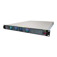
Referring to Figure 5-1,
the operator pushes the COMB MODE button to access the Combiner Menu,
uses the UP (2) and DOWN (8) arrows to scroll to Mode in blue, and then pushes ENTER or SELECT (5)
to highlight the Mode selection window in bright magenta. The operator then uses the UP (2) and DOWN
(8) arrows to select CH1, CH2 or Combined and pushes ENTER or SELECT (5).
The Combiner status is displayed on the Front Panel General Status display header bar. This header bar
is a GREEN Combiner Lock when Combined is selected and a RED Combiner Locked when either CH1
or CH2 is selected (or any Combiner Unlock condition exists). See paragraph 5.1.3 for steps required to
access the General Status display.
Selecting either CH1 or CH2 forces the selected channel through the Combiner Channel’s Demodulator,
and the Combiner Channel Video and IF Outputs on the rear panel are now the selected channel.
Figure 5-1
Front Panel Diversity Combiner Output Mode Selection
5.1.2 Combiner Output Mode on Remote GUI
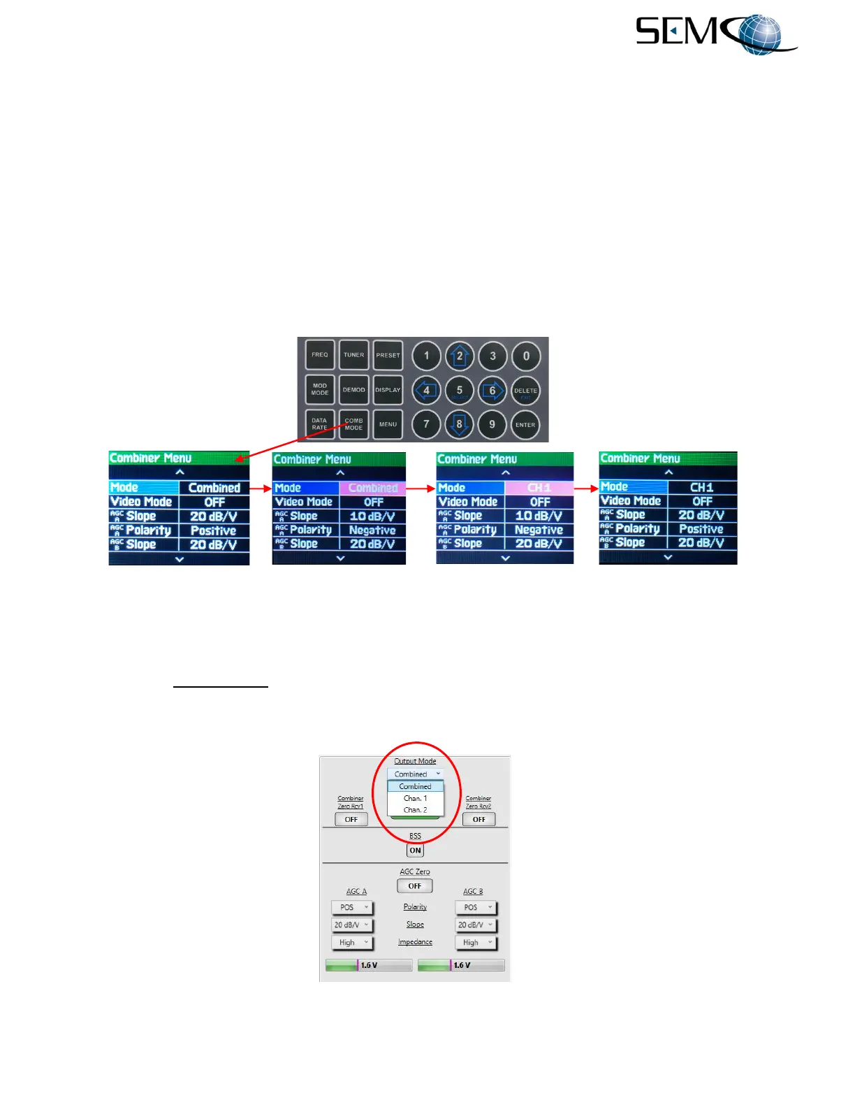
The Combiner Output Mode (Figure 5-2) is a pull-down menu that allows the user to force the combiner
to a Chan. 1, Chan. 2 or Combined output. Selecting either Chan. 1 or Chan. 2 forces the modulated IF
signal from that channel through the Combiner Channel’s Demodulator, and the Combiner Channel rear
panel Video Outputs are the baseband video outputs of the selected channel.
Figure 5-2
Diversity Combiner Output Mode on Remote GUI