A2537-002/01 February 2020 5-6 SEMCO Proprietary Information
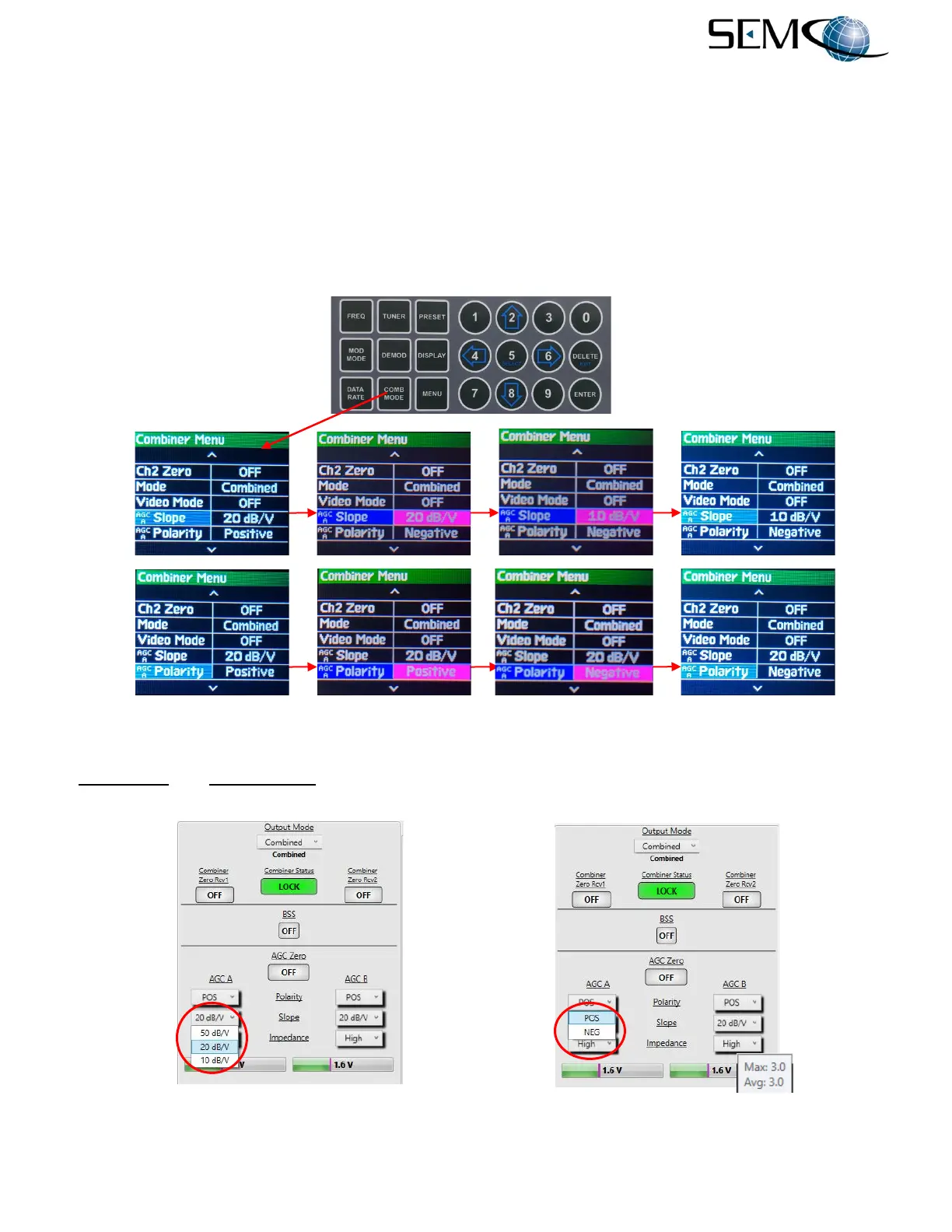
5.1.7 Combiner AGC Slope and Polarity
Figure 5-9 illustrates the steps for enabling the AGC Slope and Polarity feature using the front panel
displays and keyboard. The operator pushes the COMB MODE button to access the Combiner Menu,
uses the UP (2) and DOWN (8) arrows to scroll to AGC Slope in blue, and then pushes ENTER or SELECT
(5) to highlight the AGC Slope selection window in bright magenta. Using the UP (2) and DOWN (8)
arrows, the operator selects 10, 20 or 50 dB/V and then pushes ENTER or SELECT (5).
The operator uses the UP (2) and DOWN (8) arrows to scroll to AGC Polarity in blue, and pushes ENTER
or SELECT (5) to highlight the AGC Polarity selection window in bright magenta. Using the UP (2) and
DOWN (8) arrows, the operator selects Positive or Negative and then pushes ENTER or SELECT (5).
Figure 5-9
Front Panel Combiner AGC Slope and Polarity Selection
AGC Slope and AGC Polarity selection on the remote GUI is shown in Figure 5-10. Placing the cursor
over the AGC Voltage bar graph provides Maximum and Average AGC readouts during as shown.
Figure 5-10
Combiner AGC Slope and Polarity Selection on Remote GUI