W1: Tool offset
18.6 Toolholder with orientation capability
Basic Functions
Function Manual, 09/2011, 6FC5397-0BP40-2BA0
1509
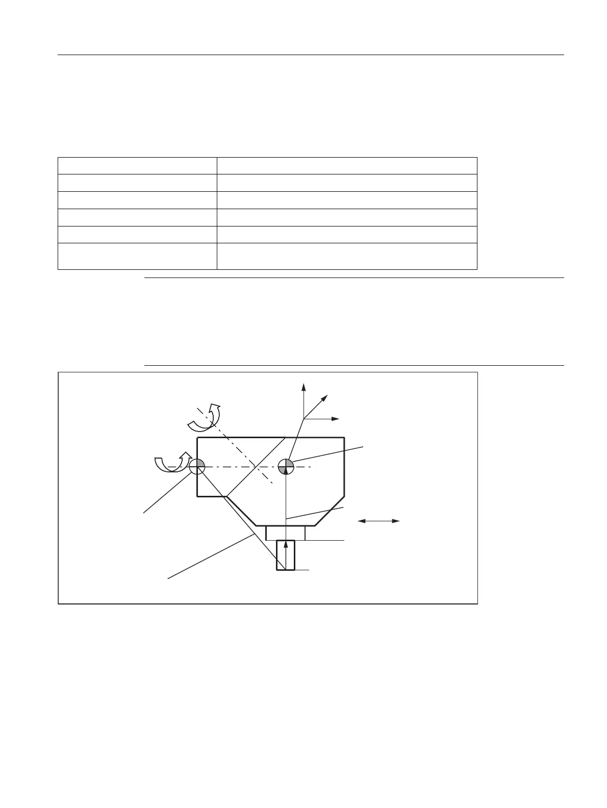
Assigning data to the toolholder
Example of a machine with rotary toolholder
The following settings are obtained at the mill head shown for a machine with toolholder with orientation
capability of kinematic type T:
Figure 18-42 Assignment of the toolholder data
Suitable assumptions were made for the following values in the data block:
Component of the offset vector l
1
= (-200, 0, 0)
Component of the offset vector l
2
= (0, 0, 0)
Component of offset vector l
3
= (-100, 0, 0)
Component of rotary axis v
1
= (1, 0, 0)
Component of rotary axis v
2
= (-1, 0, 1)
Tool base dimension of tool
reference point
(0, 0, 250)
Note
The tool reference point for the tool base dimension is defined by the reference point at the
machine.
For more information about the reference points in the working area, please refer to:
References:
/FB1/ Function Manual Basic Functions; Axes, Coordinate Systems, Frames (K2).
5HVXOWLQJWRROOHQJWKFRPSHQVDWLRQ
/HQJWK:HDU
7RROEDVHGLPHQVLRQ
7RROFDUULHUUHIHUHQFHSRLQW
$[LV
$[LV
7RROUHIHUHQFHSRLQW
[
]
\
PP
O
O
Y
Y
O

 Loading...


