Preface
Basic Functions
6 Function Manual, 09/2011, 6FC5397-0BP40-2BA0
Quantity structure
Explanations concerning the NC/PLC interface are based on the absolute maximum number of sequential
components:
• Mode groups (DB11)
• Channels (DB21, etc.)
• Axes/spindles (DB31, etc.)
Data types
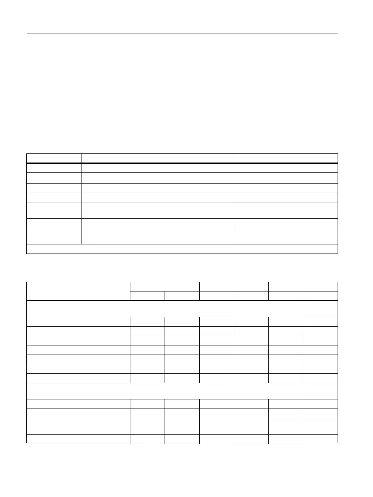
The following elementary data types are used in the control system:
SINUMERIK 828D system performance (region)
Type Meaning Value range
INT Signed integers -2147483648 ... +2147483647
REAL Figures with decimal point acc. to IEEE
±(2,2*10
-308
… 1,8*10
+308
)
BOOL Truth values TRUE (1) and FALSE (0) 1, 0
CHAR ASCII characters Corresponding to code 0 to 255
STRING Character string, number of characters in [...] Maximum of 200 characters (no special
characters)
AXIS Axis names only All axis identifiers in the channel
FRAME Geometrical parameters for moving, rotating, scaling, and
mirroring
Arrays can only be formed from similar elementary data types. Up to 3-dimensional arrays are possible.
PPU240.2 / 241.2 PPU 260.2 / 261.2 PPU 280.2 / 281.2
BASIC T BASIC M T M T M
System performance
Basic quantity of axes/spindles 3 4 3 4 3 4
Max. number of axes/spindles 5 5 6 6 8 6
Max. number of interpolating axes 4 4 4 4 4 4
Max. number: Channels / mode groups 1/1 1/1 1/1 1/1 1/1 1/1
Min. block change time ∼ 9ms ∼ 9ms ∼ 6ms ∼ 6ms ∼ 6ms ∼ 3ms
Speed/current control cycle 125µs 125µs 125µs 125µs 125µs 125µs
CNC user memory (buffered) 1 MB 1 MB 3MB 3MB 5MB 5MB
CNC functions
Tool Management ● ● ● ● ● ●
Number of tools/cutting edges 80/160 80/160 128/256 128/256 256/512 256/512
Max. number of ASUBs (permanently
set)
222222
TRANSMIT / TRACYL ○○○○○○

 Loading...


