K2: Axis Types, Coordinate Systems, Frames
10.5 Frames
Basic Functions
786 Function Manual, 09/2011, 6FC5397-0BP40-2BA0
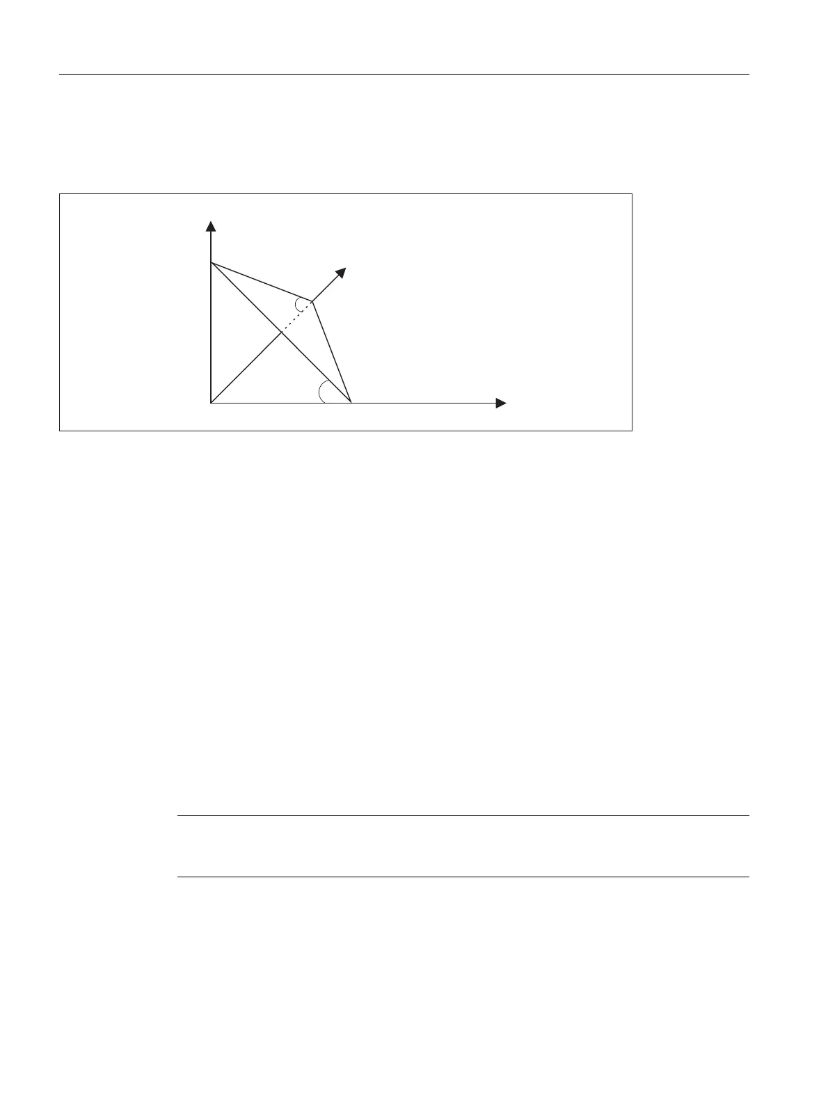
In workpiece drawings, oblique surfaces are frequently described by way of solid angles, i.e. the angles, which
the intersection lines of the oblique plane form with the main planes (X-Y, Y-Z, Z-X planes) (see figure). The
machine operator is not expected to convert these solid angles into the angles of rotation of a chaining of
individual rotations.
For this reason, the language commands ROTS, AROTS and CROTS are used, with which the rotations can be
immediately described as solid angles.
The orientation of a plane in space is defined unambiguously by specifying two solid angles. The third solid angle
is derived from the first two. Therefore, a maximum of 2 solid angles may be programmed, e.g. in the form ROTS
X10 Y15. If a third solid angle is specified, an alarm will be triggered.
It is permissible to specify a single solid angle. The rotations which are performed with ROTS or AROTS in this
case are identical to those for ROT and AROT.
An expansion of the existing functionality arises only in cases where exactly two solid angles are programmed.
The two programmed axes define a plane, the non-programmed axis defines the related third axis of a right-hand
coordinate system. Which axis is first and which second is then unambiguously defined for both programmed
axes (the definition corresponds to those found in the plane definition of G17/G18/G19). The angle programmed
with the axis letter of an axis of the plane then specifies the axis, around which the other axis of the plane must
be rotated in order to move this into the line of intersection, which the rotated plane forms with the plane
surrounded by the other and the third axis. This definition ensures that, in the case that one of the two
programmed angles is towards zero, the defined plane enters the plane, which is created if only one axis is
programmed (e.g. with ROT or AROT).
The diagram shows an example where X and Y are programmed. Y here gives the angle, by which the X axis
must rotate around the Y axis to bring the X axis to the line of intersection formed by the oblique plane and the
XZ plane. The same principle applies for the programmed value of X.
The specification of the solid angle does not define the orientation of the twodimensional coordinate system
within the plane (i.e. the angle of rotation around the surface normal vector). The position of the coordinate
system is thus determined so that the rotated first axis lies in the plane, which is surrounded by the first and third
axes of the nonrotated coordinate system.
This means that
Note
In t
he shown position of the oblique plane the value of Y is positive, that of X on the other
hand negative.
\
[
]
\
[
2EOLTXHSODQH

 Loading...


