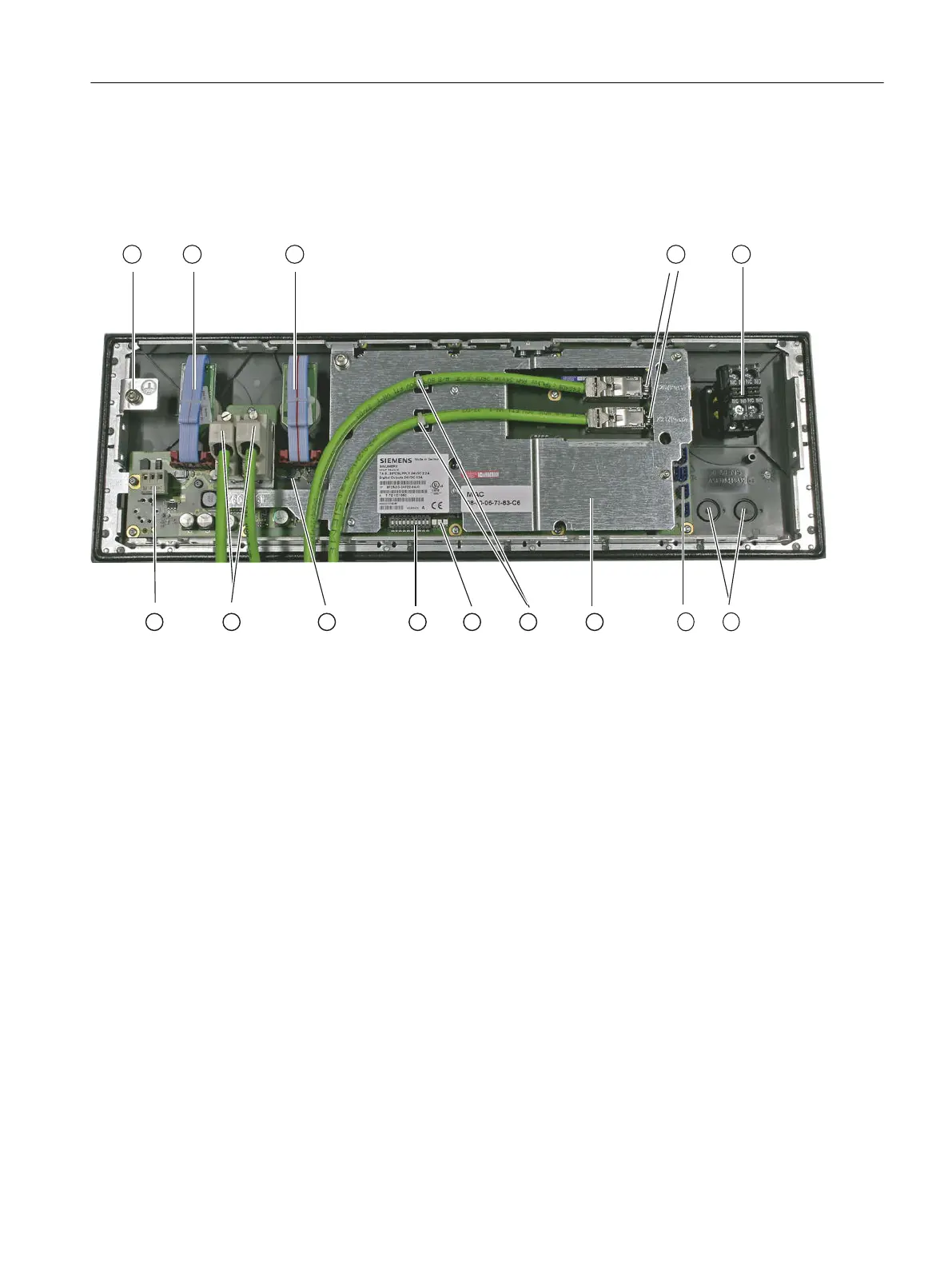
Display elements (rear)
① Ground terminal
② Feed override X30
③ Spindle override X31
④ PLC I/O Interface X20/X21 connections
⑤ Slot for emergency stop
⑥ Installation locations for additional control devices (d = 16 mm)
⑦ Customer-specific inputs and outputs
⑧ Cover plate
⑨ Ethernet cable strain relief
⑩ LEDs
⑪ Switch for setting the MCP address
⑫ Switch for setting the handwheel signal type
⑬ X60 connection for handwheel, X61 reserved
⑭ Power supply interface X10
Figure 7-12 Rear panel of MCP 483C PN
Anschließbare Komponenten
7.3 MCP 483C PN
PPU and components
Manual, 05/2015, 6FC5397-2DP40-3BA4 123

 Loading...


