Pin Signal name Signal type Meaning
4 N.C. - Not assigned
5 N.C. - Not assigned
6 RX- O Receive -
7 N.C. - Not assigned
8 N.C. - Not assigned
Rotary switch: Feed override X30 / spindle override X31
Connector designation: X30/X31
Connector type: 2 x 5-pin plug connector, according to EN 60603-13 with coding
Table 7-4 Assignment of connector X30
Pin Signal name Signal type Meaning
1 N.C. - Not assigned
2 N.C. - Not assigned
3 M V Ground
4 N.C. - Not assigned
5 P5 V 5 V supply
6 OV16
I
Rotary override switch, position/value 16
7 OV8 Rotary override switch, position/value 8
8 OV4 Rotary override switch, position/value 4
9 OV2 Rotary override switch, position/value 2
10 OV1 Rotary override switch, position/value 1
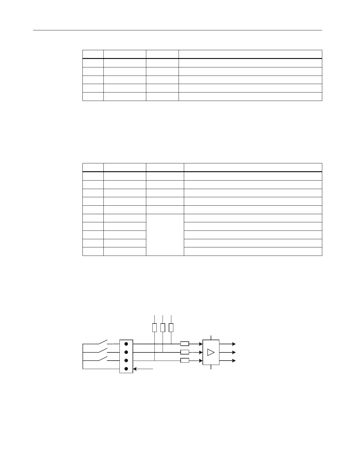
Optional customer buttons IN (X51 / X52 / X55)
Only switches (passive inputs) may be connected via the X51, X52 and X55 connectors. X51
and X52 are typically used for connecting illuminated pushbuttons. The lamps in the buttons
are activated via X53 and X54. X55 has no corresponding outputs.
;L
0
0
.7M,1
.7M,1
.7M,1
9
.
9
L
M
.
Figure 7-15 Main circuit diagram for input circuit for X51, X52 and X55
Connector designation: X51, X52, X55
Anschließbare Komponenten
7.3 MCP 483C PN
PPU and components
Manual, 05/2015, 6FC5397-2DP40-3BA4 127

 Loading...


