Connector type: 4-pin plug connector
Table 7-5 Assignment of connector X51
Pin Signal name Signal type Meaning
1 KT-IN1
I
Customer key 1
2 KT-IN2 Customer key 2
3 KT-IN3 Customer key 3
4 M V Ground
Table 7-6 Assignment of connector X52
Pin Signal name Signal type Meaning
1 KT-IN4
I
Customer key 4
2 KT-IN5 Customer key 5
3 KT-IN6 Customer key 6
4 M V Ground
Table 7-7 Assignment of connector X55
Pin Signal name Signal type Meaning
1 KT-IN7
I
Customer key 7
2 KT-IN8 Customer key 8
3 KT-IN9 Customer key 9
4 M V Ground
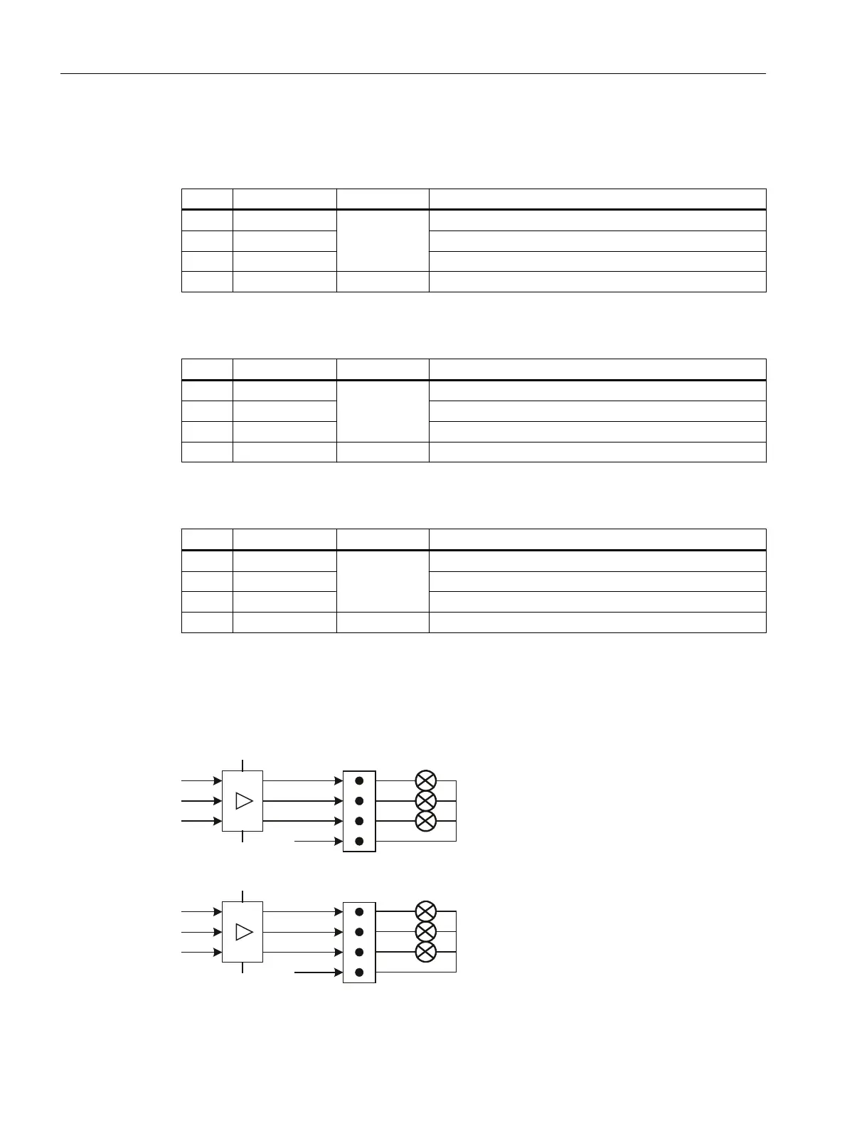
Optional customer buttons OUT (X53 / X54)
The short-circuit-proof outputs X53/X54 are provided to control lamps in the buttons. Lamps
with 24 V and 1.2 W per output are recommended.
;
0
0
3
.7287
.7287
.7287
;
0
0
3
.7287
.7287
.7287
Figure 7-16 Main circuit diagram for input circuit for X53 and X54
Anschließbare Komponenten
7.3 MCP 483C PN
PPU and components
128 Manual, 05/2015, 6FC5397-2DP40-3BA4

 Loading...


